
3. Operating Modes
Streszczenie: Tryby pracy napędu wybierane zmienną desired state (0x24): tryby prądowe (programowany, analogowy, PWM), prędkościowe (programowany, analogowy, PWM) i pozycyjne (programowany z generatorem trajektorii, analogowy, puls/kierunek, puls góra/dół, kwadratura) oraz bazowanie. Dla każdego trybu podano tabelę zmiennych i przykładową sekwencję komend.
EN: Operating modes selected with the desired state variable 0x24: current, velocity and position modes plus homing, with variable tables and command examples.
Dotyczy: serwonapędy Copley Controls z interfejsem ASCII (RS-232, sieć multi-drop CAN), program CME 2
Źródło: dokumentacja producenta (Copley Controls ASCII Interface Programmer’s Guide); tabele przepisane z obrazów na tekst – opracowanie Multiprojekt
This chapter describes the variables related to the amplifier’s operating modes. Contents include:
3.1:1 Desired State Variable
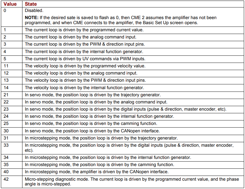
The amplifier desired state variable (0x24) defines the amplifier’s operating mode and which input source controls it. Mode-specific values are mentioned in the remaining sections of this chapter. The relevant values are described in the table below:
Desired state (variable 0x24) – values
| Value | State |
|---|---|
| 0 | Disabled. NOTE: If the desired state is saved to flash as 0, then CME 2 assumes the amplifier has not been programmed, and when CME connects to the amplifier, the Basic Set Up screen opens. |
| 1 | The current loop is driven by the programmed current value. |
| 2 | The current loop is driven by the analog command input. |
| 3 | The current loop is driven by the PWM & direction input pins. |
| 4 | The current loop is driven by the internal function generator. |
| 5 | The current loop is driven by UV commands via PWM inputs. |
| 11 | The velocity loop is driven by the programmed velocity value. |
| 12 | The velocity loop is driven by the analog command input. |
| 13 | The velocity loop is driven by the PWM & direction input pins. |
| 14 | The velocity loop is driven by the internal function generator. |
| 21 | In servo mode, the position loop is driven by the trajectory generator. |
| 22 | In servo mode, the position loop is driven by the analog command input. |
| 23 | In servo mode, the position loop is driven by the digital inputs (pulse & direction, master encoder, etc). |
| 24 | In servo mode, the position loop is driven by the internal function generator. |
| 25 | In servo mode, the position loop is driven by the camming function. |
| 30 | In servo mode, the position loop is driven by the CANopen interface. |
| 31 | In microstepping mode, the position loop is driven by the trajectory generator. |
| 33 | In microstepping mode, the position loop is driven by the digital inputs (pulse & direction, master encoder, etc). |
| 34 | In microstepping mode, the position loop is driven by the internal function generator. |
| 35 | In microstepping mode, the position loop is driven by the camming function. |
| 40 | In microstepping mode, the amplifier is driven by the CANopen interface. |
| 42 | Micro-stepping diagnostic mode. The current loop is driven by the programmed current value, and the phase angle is micro-stepped. |
Original image of the table (from the PDF manual)
3.2:2 Current Mode
3.2.1:1 Programmed Current Mode
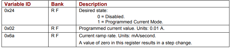
The Programmed Current Mode sets the output of the amplifier at a programmed current level. When the amplifier is enabled in this mode, or when the programmed current level is changed, the output current ramps to the new level at the programmed rate.
Programmed Current Mode Variables
| Variable ID | Bank | Description |
|---|---|---|
| 0x24 | R F | Desired state: 0 = Disabled; 1 = Programmed Current Mode. |
| 0x02 | R F | Programmed current value. Units: 0.01 A. |
| 0x6a | R F | Current ramp rate. Units: mA/second. A value of zero in this register results in a step change. |
Original image of the table (from the PDF manual)
NOTE: When changing both the level and the ramp parameters while the amplifier is enabled, change the ramp rate first.
Programmed Current Mode Example
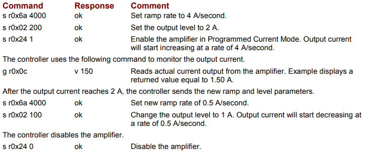
Enable the amplifier in Programmed Current Mode. Ramp the output current up to 2 A in 0.5 seconds. The controller monitors the output current, and after it reaches 2 A the current is ramped down to 1 A in 2 seconds.
| Command | Response | Comment |
|---|---|---|
| s r0x6a 4000 | ok | Set ramp rate to 4 A/second. |
| s r0x02 200 | ok | Set the output level to 2 A. |
| s r0x24 1 | ok | Enable the amplifier in Programmed Current Mode. Output current will start increasing at a rate of 4 A/second. |
| The controller uses the following command to monitor the output current. | ||
| g r0x0c | v 150 | Reads actual current output from the amplifier. Example displays a returned value equal to 1.50 A. |
| After the output current reaches 2 A, the controller sends the new ramp and level parameters. | ||
| s r0x6a 4000 | ok | Set new ramp rate of 0.5 A/second. |
| s r0x02 100 | ok | Change the output level to 1 A. Output current will start decreasing at a rate of 0.5 A/second. |
| The controller disables the amplifier. | ||
| s r0x24 0 | ok | Disable the amplifier. |
Original image of the table (from the PDF manual)
3.2.2:2 Analog Current Mode
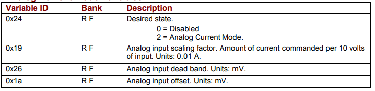
In the Analog Current Mode, the current output of the amplifier is proportional to the analog reference input command signal.
Analog Current Mode Variables
| Variable ID | Bank | Description |
|---|---|---|
| 0x24 | R F | Desired state: 0 = Disabled; 2 = Analog Current Mode. |
| 0x19 | R F | Analog input scaling factor. Amount of current commanded per 10 volts of input. Units: 0.01 A. |
| 0x26 | R F | Analog input dead band. Units: mV. |
| 0x1a | R F | Analog input offset. Units: mV. |
Original image of the table (from the PDF manual)
NOTE: Variables 0x19, 0x26 and 0x1a are used in Analog Current, Velocity and Position modes. Verify that these variables are set correctly before switching between these modes of operation.
Analog Current Mode Example
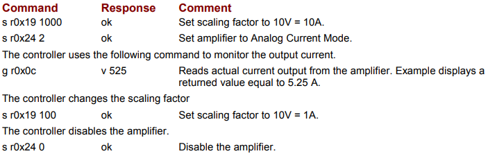
The controller sets the scaling, enables the amplifier in Analog Current Mode, monitors the current output, and changes the scaling to a new value.
| Command | Response | Comment |
|---|---|---|
| s r0x19 1000 | ok | Set scaling factor to 10V = 10A. |
| s r0x24 2 | ok | Set amplifier to Analog Current Mode. |
| The controller uses the following command to monitor the output current. | ||
| g r0x0c | v 525 | Reads actual current output from the amplifier. Example displays a returned value equal to 5.25 A. |
| The controller changes the scaling factor. | ||
| s r0x19 100 | ok | Set scaling factor to 10V = 1A. |
| The controller disables the amplifier. | ||
| s r0x24 0 | ok | Disable the amplifier. |
Original image of the table (from the PDF manual)
3.2.3:3 PWM Current Mode
In the PWM Current Mode, the current output of the amplifier is proportional to the duty cycle of the input command signal. In most applications the command signal configuration is set using CME 2 and not changed during operation.
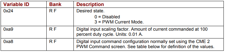
PWM Current Mode Variables
| Variable ID | Bank | Description |
|---|---|---|
| 0x24 | R F | Desired state: 0 = Disabled; 3 = PWM Current Mode. |
| 0xa9 | R F | Digital input scaling factor. Amount of current commanded at 100 percent duty cycle. Units: 0.01 A. |
| 0xa8 | R F | Digital input command configuration normally set using the CME 2 PWM Command screen. See table below for definition of the values. |
Original image of the table (from the PDF manual)
NOTE: Variables 0xa9 and 0xa8 are used in PWM Current and Velocity modes. Verify that these variables are set correctly before switching between these modes of operation.
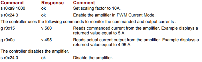
PWM Current Mode Example
The controller sets the scaling, enables the amplifier in PWM Current Mode, and monitors commanded and actual current.
| Command | Response | Comment |
|---|---|---|
| s r0xa9 1000 | ok | Set scaling factor to 10A. |
| s r0x24 3 | ok | Enable the amplifier in PWM Current Mode. |
| The controller uses the following commands to monitor the commanded and output currents. | ||
| g r0x15 | v 500 | Reads commanded current from the amplifier. Example displays a returned value equal to 5 A. |
| g r0x0c | v 495 | Reads actual current output from the amplifier. Example displays a returned value equal to 4.95 A. |
| The controller disables the amplifier. | ||
| s r0x24 0 | ok | Disable the amplifier. |
Original image of the table (from the PDF manual)
PWM Current Mode Command Signal Configuration
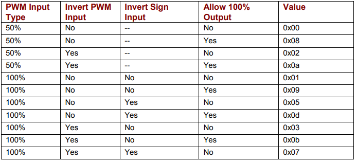
If required during operation, the PWM command signal configuration can be changed by setting the value of variable 0xa8 as shown below
Values of variable 0xa8 (PWM input configuration)
| PWM Input Type | Invert PWM Input | Invert Sign Input | Allow 100% Output | Value |
|---|---|---|---|---|
| 50% | No | -- | No | 0x00 |
| 50% | No | -- | Yes | 0x08 |
| 50% | Yes | -- | No | 0x02 |
| 50% | Yes | -- | Yes | 0x0a |
| 100% | No | No | No | 0x01 |
| 100% | No | No | Yes | 0x09 |
| 100% | No | Yes | No | 0x05 |
| 100% | No | Yes | Yes | 0x0d |
| 100% | Yes | No | No | 0x03 |
| 100% | Yes | No | Yes | 0x0b |
| 100% | Yes | Yes | No | 0x07 |
Original image of the table (from the PDF manual)
3.3:3 Velocity Mode
3.3.1:1 Programmed Velocity Mode
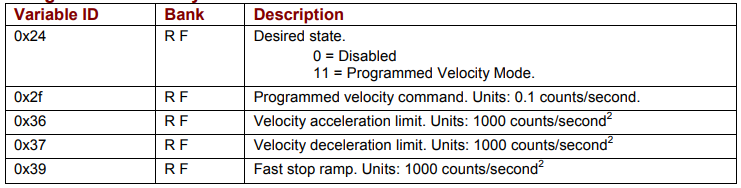
The Programmed Velocity Mode sets the output of the amplifier to a programmed motor velocity. When the amplifier is enabled in this mode, or when the programmed velocity is changed, the motor velocity will ramp to the new level at the programmed rate.
Programmed Velocity Mode Variables
| Variable ID | Bank | Description |
|---|---|---|
| 0x24 | R F | Desired state: 0 = Disabled; 11 = Programmed Velocity Mode. |
| 0x2f | R F | Programmed velocity command. Units: 0.1 counts/second. |
| 0x36 | R F | Velocity acceleration limit. Units: 1000 counts/second². |
| 0x37 | R F | Velocity deceleration limit. Units: 1000 counts/second². |
| 0x39 | R F | Fast stop ramp. Units: 1000 counts/second². |
Original image of the table (from the PDF manual)
Programmed Velocity Mode Example
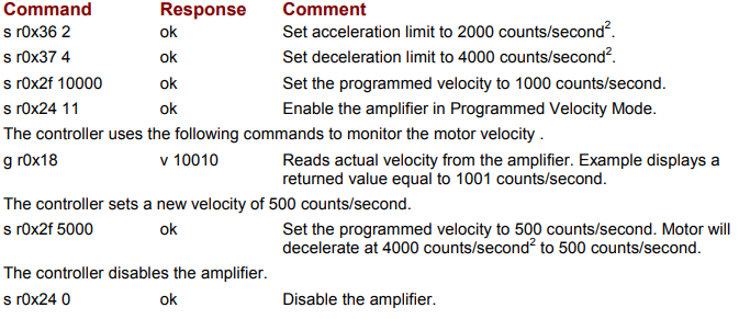
The controller sets the velocity parameters, enables the amplifier in Programmed Velocity Mode, monitors the actual motor velocity, and then changes the velocity.
| Command | Response | Comment |
|---|---|---|
| s r0x36 2 | ok | Set acceleration limit to 2000 counts/second². |
| s r0x37 4 | ok | Set deceleration limit to 4000 counts/second². |
| s r0x2f 10000 | ok | Set the programmed velocity to 1000 counts/second. |
| s r0x24 11 | ok | Enable the amplifier in Programmed Velocity Mode. |
| The controller uses the following commands to monitor the motor velocity. | ||
| g r0x18 | v 10010 | Reads actual velocity from the amplifier. Example displays a returned value equal to 1001 counts/second. |
| The controller sets a new velocity of 500 counts/second. | ||
| s r0x2f 5000 | ok | Set the programmed velocity to 500 counts/second. Motor will decelerate at 4000 counts/second² to 500 counts/second. |
| The controller disables the amplifier. | ||
| s r0x24 0 | ok | Disable the amplifier. |
Original image of the table (from the PDF manual)
3.3.2:2 Analog Velocity Mode
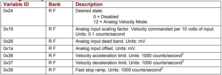
In the Analog Velocity Mode, the motor velocity is proportional to the analog reference input command signal.
Analog Velocity Mode Variables
| Variable ID | Bank | Description |
|---|---|---|
| 0x24 | R F | Desired state: 0 = Disabled; 12 = Analog Velocity Mode. |
| 0x19 | R F | Analog input scaling factor. Velocity commanded per 10 volts of input. Units: 0.1 counts/second. |
| 0x26 | R F | Analog input dead band. Units: mV. |
| 0x1a | R F | Analog input offset. Units: mV. |
| 0x36 | R F | Velocity acceleration limit. Units: 1000 counts/second². |
| 0x37 | R F | Velocity deceleration limit. Units: 1000 counts/second². |
| 0x39 | R F | Fast stop ramp. Units: 1000 counts/second². |
Original image of the table (from the PDF manual)
NOTE: Variables 0x19, 0x26 and 0x1a are used in Analog Current, Velocity and Position modes. Verify that these variables are set correctly before switching between these modes of operation.
Analog Velocity Mode Example
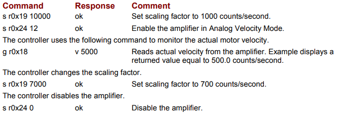
The controller sets the scaling, enables the amplifier in Analog Velocity Mode, monitors the actual motor velocity, and changes the scaling.
| Command | Response | Comment |
|---|---|---|
| s r0x19 10000 | ok | Set scaling factor to 1000 counts/second. |
| s r0x24 12 | ok | Enable the amplifier in Analog Velocity Mode. |
| The controller uses the following command to monitor the actual motor velocity. | ||
| g r0x18 | v 5000 | Reads actual velocity from the amplifier. Example displays a returned value equal to 500.0 counts/second. |
| The controller changes the scaling factor. | ||
| s r0x19 7000 | ok | Set scaling factor to 700 counts/second. |
| The controller disables the amplifier. | ||
| s r0x24 0 | ok | Disable the amplifier. |
Original image of the table (from the PDF manual)
3.3.3:3 PWM Velocity Mode
In the PWM Velocity Mode, the motor velocity is proportional to the duty cycle of the input command signal. In most applications the command signal configuration is set using CME 2 and not changed during operation.
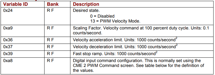
PWM Velocity Mode Variables
| Variable ID | Bank | Description |
|---|---|---|
| 0x24 | R F | Desired state: 0 = Disabled; 13 = PWM Velocity Mode. |
| 0xa9 | R F | Scaling Factor. Velocity command at 100 percent duty cycle. Units: 0.1 counts/second. |
| 0x36 | R F | Velocity acceleration limit. Units: 1000 counts/second². |
| 0x37 | R F | Velocity deceleration limit. Units: 1000 counts/second². |
| 0x39 | R F | Fast stop ramp. Units: 1000 counts/second². |
| 0xa8 | R F | Digital input command configuration. This is normally set using the CME 2 PWM Command screen. See table below for the definition of the values. |
Original image of the table (from the PDF manual)
NOTE: Variables 0xa9 and 0xa8 are used in PWM Current and Velocity modes. Verify that these variables are set correctly before switching between these modes of operation.
PWM Velocity Mode Example
The controller sets the PWM scaling, enables the amplifier in PWM Velocity Mode, and monitors the commanded and actual velocity.
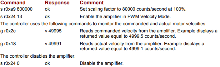
| Command | Response | Comment |
|---|---|---|
| s r0xa9 800000 | ok | Set scaling factor to 80000 counts/second at 100%. |
| s r0x24 13 | ok | Enable the amplifier in PWM Velocity Mode. |
| The controller uses the following commands to monitor the commanded and actual motor velocities. | ||
| g r0x2c | v 49995 | Reads commanded velocity from the amplifier. Example displays a returned value equal to 4999.5 counts/second. |
| g r0x18 | v 49991 | Reads actual velocity from the amplifier. Example displays a returned value equal to 4999.1 counts/second. |
| The controller disables the amplifier. | ||
| s r0x24 0 | ok | Disable the amplifier. |
Original image of the table (from the PDF manual)
PWM Velocity Mode Command Signal Configuration
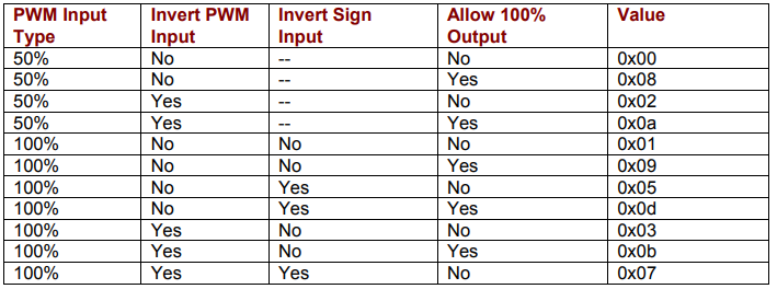
If required during operation, the PWM command signal configuration can be changed by setting the value of variable 0xa8 as shown below.
Values of variable 0xa8 (PWM input configuration)
| PWM Input Type | Invert PWM Input | Invert Sign Input | Allow 100% Output | Value |
|---|---|---|---|---|
| 50% | No | -- | No | 0x00 |
| 50% | No | -- | Yes | 0x08 |
| 50% | Yes | -- | No | 0x02 |
| 50% | Yes | -- | Yes | 0x0a |
| 100% | No | No | No | 0x01 |
| 100% | No | No | Yes | 0x09 |
| 100% | No | Yes | No | 0x05 |
| 100% | No | Yes | Yes | 0x0d |
| 100% | Yes | No | No | 0x03 |
| 100% | Yes | No | Yes | 0x0b |
| 100% | Yes | Yes | No | 0x07 |
Original image of the table (from the PDF manual)
3.4:4 Position Mode
3.4.1:1 Updating Trajectory Variables in Position Modes
When the amplifier enters a position mode, the trajectory variables (velocity, acceleration and deceleration) are copied into the trajectory generator. To change any of them after the amplifier is in a position mode, send the new value to the appropriate variable and then send a t 1command.
3.4.2:2 Programmed Position Mode
In the Programmed Position Mode, the axis moves to target positions sent to the amplifier over the serial interface. The target positions can be absolute or relative from the current position. The motion profile used can be set to trapezoidal or S-curve.
To initiate a move, first set the appropriate variables and then send the trajectory command t 1 to start the move (see Trajectory (t) Generator Command, p. 17). When using the trapezoidal profile, the move parameters can be changed during the move. Again, first set the appropriate variables and then send another t 1 command. When the t 1 command is received, the target position, absolute / relative, velocity, acceleration and deceleration rates will be updated. In this manner, the move in progress can be changed. The S-curve profile cannot be updated in this manner.
To abort a move in progress, send a t 0 command. This will stop the move in progress using the abort deceleration rate. The amplifier will remain enabled.
A special velocity mode can be used to move the axis using the velocity, acceleration and deceleration of the trapezoidal profile but with no specific target position. Direction of motion is set by entering a “1” or “-1” into the position command variable. Once started, the move will continue until the velocity variable is set to zero and a t 1 command is sent or a t 0 abort command is sent.
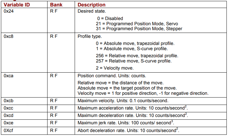
Programmed Position Mode Variables
| Variable ID | Bank | Description |
|---|---|---|
| 0x24 | R F | Desired state: 0 = Disabled; 21 = Programmed Position Mode, Servo; 31 = Programmed Position Mode, Stepper. |
| 0xc8 | R F | Profile type: 0 = Absolute move, trapezoidal profile; 1 = Absolute move, S-curve profile; 256 = Relative move, trapezoidal profile; 257 = Relative move, S-curve profile; 2 = Velocity move. |
| 0xca | R F | Position command. Units: counts. Relative move = the distance of the move. Absolute move = the target position of the move. Velocity move = 1 for positive direction, -1 for negative direction. |
| 0xcb | R F | Maximum velocity. Units: 0.1 counts/second. |
| 0xcc | R F | Maximum acceleration rate. Units: 10 counts/second². |
| 0xcd | R F | Maximum deceleration rate. Units: 10 counts/second². |
| 0xce | R F | Maximum jerk rate. Units: 100 counts/second³. |
| 0xcf | R F | Abort deceleration rate. Units: 10 counts/second². |
Original image of the table (from the PDF manual)
NOTES: 1) Maximum jerk rate is not used in the trapezoidal profile. 2) In the S-curve profile, the maximum deceleration rate is note used. The maximum acceleration rate is used for both acceleration and deceleration.
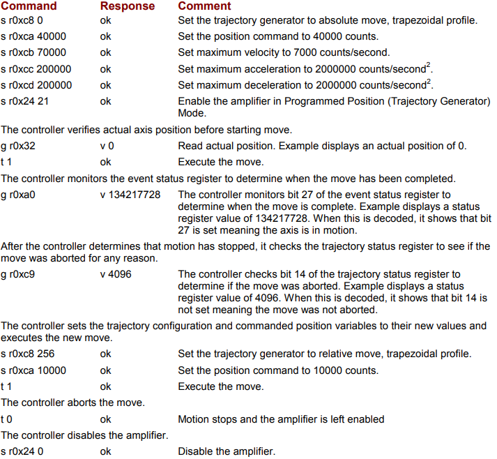
Programmed Position Mode Example
The controller sets profile parameters, executes an absolute trapezoidal move to position 40,000 counts, monitors for move completion, and then executes a relative move of 10,000 counts using the same profile parameters.
| Command | Response | Comment |
|---|---|---|
| s r0xc8 0 | ok | Set the trajectory generator to absolute move, trapezoidal profile. |
| s r0xca 40000 | ok | Set the position command to 40000 counts. |
| s r0xcb 70000 | ok | Set maximum velocity to 7000 counts/second. |
| s r0xcc 200000 | ok | Set maximum acceleration to 2000000 counts/second². |
| s r0xcd 200000 | ok | Set maximum deceleration to 2000000 counts/second². |
| s r0x24 21 | ok | Enable the amplifier in Programmed Position (Trajectory Generator) Mode. |
| The controller verifies actual axis position before starting move. | ||
| g r0x32 | v 0 | Read actual position. Example displays an actual position of 0. |
| t 1 | ok | Execute the move. |
| The controller monitors the event status register to determine when the move has been completed. | ||
| g r0xa0 | v 134217728 | The controller monitors bit 27 of the event status register to determine when the move is complete. Example displays a status register value of 134217728. When this is decoded, it shows that bit 27 is set meaning the axis is in motion. |
| After the controller determines that motion has stopped, it checks the trajectory status register to see if the move was aborted for any reason. | ||
| g r0xc9 | v 4096 | The controller checks bit 14 of the trajectory status register to determine if the move was aborted. Example displays a status register value of 4096. When this is decoded, it shows that bit 14 is not set meaning the move was not aborted. |
| The controller sets the trajectory configuration and commanded position variables to their new values and executes the new move. | ||
| s r0xc8 256 | ok | Set the trajectory generator to relative move, trapezoidal profile. |
| s r0xca 10000 | ok | Set the position command to 10000 counts. |
| t 1 | ok | Execute the move. |
| The controller aborts the move. | ||
| t 0 | ok | Motion stops and the amplifier is left enabled. |
| The controller disables the amplifier. | ||
| s r0x24 0 | ok | Disable the amplifier. |
Original image of the table (from the PDF manual)
3.4.3:3 Analog Position Mode
In the Analog Position Mode, the axis position is commanded by the analog reference input command signal.
The analog position command operates as a relative motion command. When the amplifier is enabled the voltage on the analog input is read. Then any change in the command voltage will move the axis a relative distance, equal to the change in voltage, from its position when enabled.
To use the analog position command as an absolute position command, the amplifier should be homed every time it is enabled.
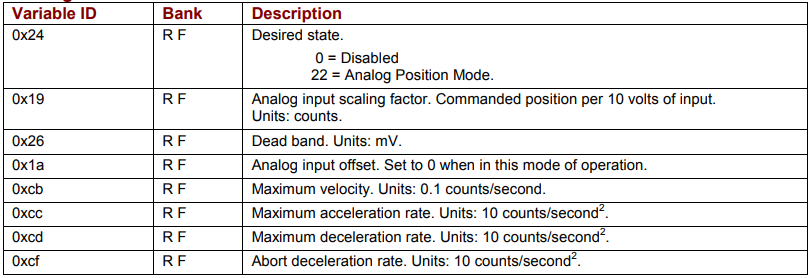
Analog Position Mode Variables
| Variable ID | Bank | Description |
|---|---|---|
| 0x24 | R F | Desired state: 0 = Disabled; 22 = Analog Position Mode. |
| 0x19 | R F | Analog input scaling factor. Commanded position per 10 volts of input. Units: counts. |
| 0x26 | R F | Dead band. Units: mV. |
| 0x1a | R F | Analog input offset. Set to 0 when in this mode of operation. |
| 0xcb | R F | Maximum velocity. Units: 0.1 counts/second. |
| 0xcc | R F | Maximum acceleration rate. Units: 10 counts/second². |
| 0xcd | R F | Maximum deceleration rate. Units: 10 counts/second². |
| 0xcf | R F | Abort deceleration rate. Units: 10 counts/second². |
Original image of the table (from the PDF manual)
NOTES: 1) Variables 0x19, 0x26 and 0x1a are used in Analog Current, Velocity and Position modes. Verify that these variables are set correctly before switching between these modes of operation. 2) To invert the direction of motion with respect to the polarity of the command voltage, set the scaling factor as a negative value.
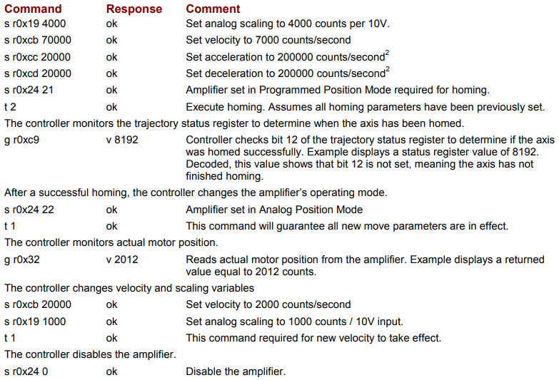
Analog Position Mode Example
The controller sets the move parameters, homes the axis and then places the amp in the Analog Position Mode. The controller monitors actual position. The controller then changes the maximum velocity and scaling factor.
| Command | Response | Comment |
|---|---|---|
| s r0x19 4000 | ok | Set analog scaling to 4000 counts per 10V. |
| s r0xcb 70000 | ok | Set velocity to 7000 counts/second. |
| s r0xcc 20000 | ok | Set acceleration to 200000 counts/second². |
| s r0xcd 20000 | ok | Set deceleration to 200000 counts/second². |
| s r0x24 21 | ok | Amplifier set in Programmed Position Mode required for homing. |
| t 2 | ok | Execute homing. Assumes all homing parameters have been previously set. |
| The controller monitors the trajectory status register to determine when the axis has been homed. | ||
| g r0xc9 | v 8192 | Controller checks bit 12 of the trajectory status register to determine if the axis was homed successfully. Example displays a status register value of 8192. Decoded, this value shows that bit 12 is not set, meaning the axis has not finished homing. |
| After a successful homing, the controller changes the amplifier’s operating mode. | ||
| s r0x24 22 | ok | Amplifier set in Analog Position Mode. |
| t 1 | ok | This command will guarantee all new move parameters are in effect. |
| The controller monitors actual motor position. | ||
| g r0x32 | v 2012 | Reads actual motor position from the amplifier. Example displays a returned value equal to 2012 counts. |
| The controller changes velocity and scaling variables. | ||
| s r0xcb 20000 | ok | Set velocity to 2000 counts/second. |
| s r0x19 1000 | ok | Set analog scaling to 1000 counts / 10V input. |
| t 1 | ok | This command required for new velocity to take effect. |
| The controller disables the amplifier. | ||
| s r0x24 0 | ok | Disable the amplifier. |
Original image of the table (from the PDF manual)
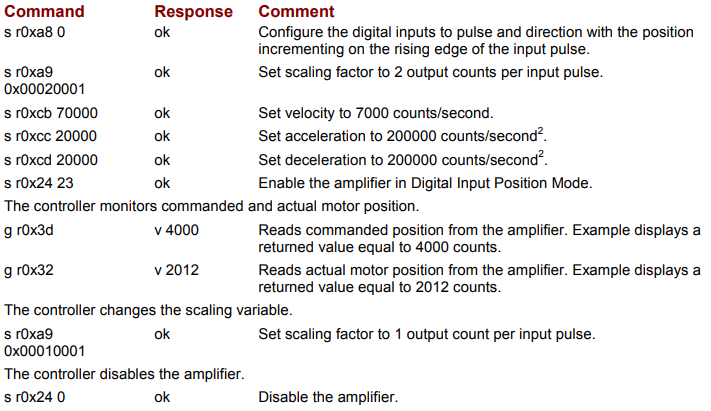
3.4.4:4 Pulse and Direction Mode
In the Pulse and Direction Position Mode, the axis position is commanded by pulses applied to one of the amplifiers digital inputs. The direction of the commanded move is determined by the logic level of a second digital input.
The scaling factor sets the ratio of position command, in counts, for each input pulse. This ratio is stored in variable 0xa9 as two 16 bit words. The first word stores the numerator or number of position counts. The second stores the denominator or the number of input pulses.
Example: To set a ratio of 10 counts of position change for every input pulse. The ration would be 10/1. To make sending the data easier, it should be converted to hex word format so the ratio would now be 0x000a / 0x0001. The two words can now simply be combined and sent to the amplifier by sending the command s r0xa9 0x000a0001.
To invert the direction, the numerator should be set to a negative value.
Example: Changing direction of the previous example would require a ratio of -10/1. Using the 2’s complement method, -10 is represented as 0xfff6 hex. The ratio in hex would now be 0xfff6 / 0x001. Combining these words, the command to be sent would be s r0xa9 0xfff60001.
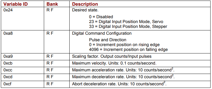
Pulse and Direction Mode Variables
| Variable ID | Bank | Description |
|---|---|---|
| 0x24 | R F | Desired state: 0 = Disabled; 23 = Digital Input Position Mode, Servo; 33 = Digital Input Position Mode, Stepper. |
| 0xa8 | R F | Digital Command Configuration – Pulse and Direction: 0 = Increment position on rising edge; 4096 = Increment position on falling edge. |
| 0xa9 | R F | Scaling factor. Output counts/Input pulses. |
| 0xcb | R F | Maximum velocity. Units: 0.1 counts/second. |
| 0xcc | R F | Maximum acceleration rate. Units: 10 counts/second². |
| 0xcd | R F | Maximum deceleration rate. Units: 10 counts/second². |
| 0xcf | R F | Abort deceleration rate. Units: 10 counts/second². |
Original image of the table (from the PDF manual)
Pulse and Direction Mode Example
The controller sets the move parameters, places the amp in the Pulse and Direction Position Mode, monitors commanded and actual position, and then changes the scaling factor
| Command | Response | Comment |
|---|---|---|
| s r0xa8 0 | ok | Configure the digital inputs to pulse and direction with the position incrementing on the rising edge of the input pulse. |
| s r0xa9 0x00020001 | ok | Set scaling factor to 2 output counts per input pulse. |
| s r0xcb 70000 | ok | Set velocity to 7000 counts/second. |
| s r0xcc 20000 | ok | Set acceleration to 200000 counts/second². |
| s r0xcd 20000 | ok | Set deceleration to 200000 counts/second². |
| s r0x24 23 | ok | Enable the amplifier in Digital Input Position Mode. |
| The controller monitors commanded and actual motor position. | ||
| g r0x3d | v 4000 | Reads commanded position from the amplifier. Example displays a returned value equal to 4000 counts. |
| g r0x32 | v 2012 | Reads actual motor position from the amplifier. Example displays a returned value equal to 2012 counts. |
| The controller changes the scaling variable. | ||
| s r0xa9 0x00010001 | ok | Set scaling factor to 1 output count per input pulse. |
| The controller disables the amplifier. | ||
| s r0x24 0 | ok | Disable the amplifier. |
Original image of the table (from the PDF manual)
3.4.5:5 Pulse Up/Down Mode
In the Pulse Up/Down Position Mode, the axis position is commanded by pulses applied to the amplifiers digital inputs. The direction of the commanded move is determined by which of the digital inputs the pulses are applied to.
The scaling factor sets the ratio of position command, in counts, for each input pulse. It is stored in variable 0xa9 as two 16 bit words. The first word stores the numerator or number of position counts. The second stores the denominator or the number of input pulses.
Example: To set a ratio of 10 counts of position change for every input pulse. The ration would be 10/1. To make sending the data easier, it should be converted to hex word format so the ratio would now be 0x000a / 0x0001. The two words can now simply be combined and sent to the amplifier by sending the command s r0xa9 0x000a0001. To invert the direction, the numerator should be set to a negative value.
Example: Changing direction of the previous example would require a ratio of -10/1. Using the 2’s complement method, -10 is represented as 0xfff6 in hex format. The ratio in hex format would now be 0xfff6 / 0x001. Combining these words, the command to be sent would be s r0xa9 0xfff60001.
Pulse Up/Down Mode Variables
| Variable ID | Bank | Description |
|---|---|---|
| 0x24 | R F | Desired state: 0 = Disabled; 23 = Digital Input Position Mode, Servo; 33 = Digital Input Position Mode, Stepper. |
| 0xa8 | R F | Digital Command Configuration – Pulse Up/Down Mode: 256 = Increment position on rising edge; 4352 = Increment position on falling edge. |
| 0xa9 | R F | Input / Output Ratio. |
| 0xcb | R F | Maximum velocity. Units: 0.1 counts/second. |
| 0xcc | R F | Maximum acceleration rate. Units: 10 counts/second². |
| 0xcd | R F | Maximum deceleration rate. Units: 10 counts/second². |
| 0xcf | R F | Abort deceleration rate. Units: 10 counts/second². |
Original image of the table (from the PDF manual)
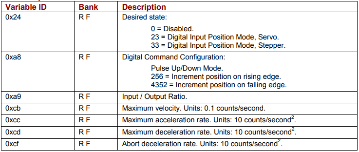
Pulse Up/Down Mode Example
The controller sets the move parameters and then places the amp in the Pulse Up/Down Position Mode, monitors commanded and actual position, and then changes the scaling factor.
| Command | Response | Comment |
|---|---|---|
| s r0xa8 256 | ok | Configure the digital inputs to pulse up/down with the position incrementing on the rising edge of the input pulse. |
| s r0xa9 0x000f0001 | ok | Set scaling factor to 15 output counts per input pulse. |
| s r0xcb 70000 | ok | Set velocity to 7000 counts/second. |
| s r0xcc 20000 | ok | Set acceleration to 200000 counts/second². |
| s r0xcd 20000 | ok | Set deceleration to 200000 counts/second². |
| s r0x24 23 | ok | Enable the amplifier in Digital Input Position Mode. |
| The controller monitors commanded and actual motor position. | ||
| g r0x3d | v 4000 | Reads commanded position from the amplifier. Example displays a returned value equal to 4000 counts. |
| g r0x32 | v 2012 | Reads actual motor position from the amplifier. Example displays a returned value equal to 2012 counts. |
| The controller changes the scaling variable. | ||
| s r0xa9 0x00010001 | ok | Set scaling factor to 1 output count per input pulse. |
| The controller disables the amplifier. | ||
| s r0x24 0 | ok | Disable the amplifier. |
Original image of the table (from the PDF manual)
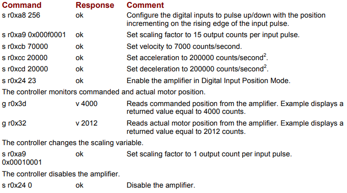
3.4.6:6 Quadrature Mode
In the Quadrature Position Mode, the axis position is commanded by a master encoder with its A and B channels applied to the amplifier’s digital inputs.
The scaling factor sets the ratio of position command, in counts, for each count of the master encoder. The scaling factor is stored in 0xa9 as two 16 bit words. Word 1 stores the numerator or number of position counts. Word 2 stores the denominator or the number of input counts.
Example: To set a ratio of 10 counts of position change for every input count, the ratio would be 10/1. To make sending the data easier, the ratio should be converted to its hex equivalent (0x000a/0x0001). The two words can now be combined and sent to the amplifier by sending the command s r0xa9 0x000a0001.
To invert the direction, the numerator should be set to a negative value.
Example: Changing direction of the previous example would require a ratio of -10/1. Using the 2’s complement method, -10 is represented as 0xfff6 in hex format. The ratio in hex format would now be 0xfff6/0x001. Combining these words, the command to be sent would be s r0xa9 0xfff60001.
Quadrature Mode Variables
| Variable ID | Bank | Description |
|---|---|---|
| 0x24 | R F | Desired state: 0 = Disabled; 23 = Digital Input Position Mode, Servo; 33 = Digital Input Position Mode, Stepper. |
| 0xa8 | R F | Digital Command Configuration: 512 = Quadrature Mode. |
| 0xa9 | R F | Input / Output Ratio. |
| 0xcb | R F | Maximum velocity. Units: 0.1 counts/second. |
| 0xcc | R F | Maximum acceleration rate. Units: 10 counts/second². |
| 0xcd | R F | Maximum deceleration rate. Units: 10 counts/second². |
| 0xcf | R F | Abort deceleration rate. Units: 10 counts/second². |
Original image of the table (from the PDF manual)
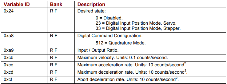
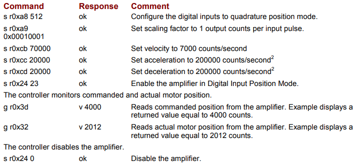
Quadrature Mode Example
The controller sets the move parameters, enables the amplifier in the Quadrature Position Mode, and monitors commanded and actual position.
| Command | Response | Comment |
|---|---|---|
| s r0xa8 512 | ok | Configure the digital inputs to quadrature position mode. |
| s r0xa9 0x00010001 | ok | Set scaling factor to 1 output counts per input pulse. |
| s r0xcb 70000 | ok | Set velocity to 7000 counts/second. |
| s r0xcc 20000 | ok | Set acceleration to 200000 counts/second². |
| s r0xcd 20000 | ok | Set deceleration to 200000 counts/second². |
| s r0x24 23 | ok | Enable the amplifier in Digital Input Position Mode. |
| The controller monitors commanded and actual motor position. | ||
| g r0x3d | v 4000 | Reads commanded position from the amplifier. Example displays a returned value equal to 4000 counts. |
| g r0x32 | v 2012 | Reads actual motor position from the amplifier. Example displays a returned value equal to 2012 counts. |
| The controller disables the amplifier. | ||
| s r0x24 0 | ok | Disable the amplifier. |
Original image of the table (from the PDF manual)
3.4.7:7 Homing Mode
Homing sequences can be performed using the t 2 command when the amplifier is in Programmed Position Mode (servo or stepper). In most applications the homing sequence is configured using CME 2 and not changed during operation.
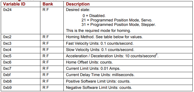
Homing Mode Variables
| Variable ID | Bank | Description |
|---|---|---|
| 0x24 | R F | Desired state: 0 = Disabled; 21 = Programmed Position Mode, Servo; 31 = Programmed Position Mode, Stepper. This is the required mode for homing. |
| 0xc2 | R F | Homing Method. See table below for values. |
| 0xc3 | R F | Fast Velocity. Units: 0.1 counts/second. |
| 0xc4 | R F | Slow Velocity. Units: 0.1 counts/second. |
| 0xc5 | R F | Acceleration / Deceleration. Units: 10 counts/second². |
| 0xc6 | R F | Home Offset. Units: counts. |
| 0xc7 | R F | Current Limit. Units: 0.01 Amps. |
| 0xbf | R F | Current Delay Time. Units: milliseconds. |
| 0xb8 | R F | Positive Software Limit. Units: counts. |
| 0xb9 | R F | Negative Software Limit. Units: counts. |
Original image of the table (from the PDF manual)
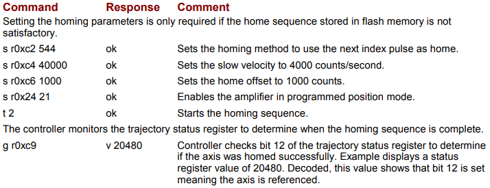
Homing Example
The controller modifies the homing parameters, enables the amplifier in the Programmed Position Mode, initiates a homing sequence and then monitors homing status
| Command | Response | Comment |
|---|---|---|
| Setting the homing parameters is only required if the home sequence stored in flash memory is not satisfactory. | ||
| s r0xc2 544 | ok | Sets the homing method to use the next index pulse as home. |
| s r0xc4 40000 | ok | Sets the slow velocity to 4000 counts/second. |
| s r0xc6 1000 | ok | Sets the home offset to 1000 counts. |
| s r0x24 21 | ok | Enables the amplifier in programmed position mode. |
| t 2 | ok | Starts the homing sequence. |
| The controller monitors the trajectory status register to determine when the homing sequence is complete. | ||
| g r0xc9 | v 20480 | Controller checks bit 12 of the trajectory status register to determine if the axis was homed successfully. Example displays a status register value of 20480. Decoded, this value shows that bit 12 is set meaning the axis is referenced. |
Original image of the table (from the PDF manual)
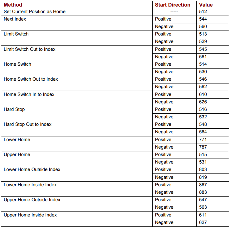
Homing Methods (0xc2)
For a full description of the methods listed below, see Homing Method Descriptions
Homing methods – values of variable 0xc2
| Method | Start Direction | Value |
|---|---|---|
| Set Current Position as Home | ----- | 512 |
| Next Index | Positive | 544 |
| Next Index | Negative | 560 |
| Limit Switch | Positive | 513 |
| Limit Switch | Negative | 529 |
| Limit Switch Out to Index | Positive | 545 |
| Limit Switch Out to Index | Negative | 561 |
| Home Switch | Positive | 514 |
| Home Switch | Negative | 530 |
| Home Switch Out to Index | Positive | 546 |
| Home Switch Out to Index | Negative | 562 |
| Home Switch In to Index | Positive | 610 |
| Home Switch In to Index | Negative | 626 |
| Hard Stop | Positive | 516 |
| Hard Stop | Negative | 532 |
| Hard Stop Out to Index | Positive | 548 |
| Hard Stop Out to Index | Negative | 564 |
| Lower Home | Positive | 771 |
| Lower Home | Negative | 787 |
| Upper Home | Positive | 515 |
| Upper Home | Negative | 531 |
| Lower Home Outside Index | Positive | 803 |
| Lower Home Outside Index | Negative | 819 |
| Lower Home Inside Index | Positive | 867 |
| Lower Home Inside Index | Negative | 883 |
| Upper Home Outside Index | Positive | 547 |
| Upper Home Outside Index | Negative | 563 |
| Upper Home Inside Index | Positive | 611 |
| Upper Home Inside Index | Negative | 627 |
Original image of the table (from the PDF manual)
Słowa kluczowe
desired state, 0x24, tryb prądowy, current mode, tryb prędkościowy, velocity mode, tryb pozycyjny, position mode, generator trajektorii, trajectory generator, analog, PWM, pulse and direction, pulse up/down, quadrature, homing, bazowanie, 0xa8, 0xa9, 0xc8, 0xca