
4. Operation
Streszczenie: Obsługa napędu przez ASCII: ustawianie prędkości transmisji, limitów i wzmocnień pętli prądowej, prędkościowej i pozycyjnej oraz filtrów, monitorowanie rejestrów statusu (0xa0), trajektorii (0xc9) i błędów (0xa4), odczyt zmiennych bieżących oraz odczyt wejść i ustawianie wyjść cyfrowych.
EN: Operation: baud rate, loop limits and gains, filters, status/trajectory/fault registers, run-time variables, digital inputs and outputs.
Dotyczy: serwonapędy Copley Controls z interfejsem ASCII (RS-232, sieć multi-drop CAN), program CME 2
Źródło: dokumentacja producenta (Copley Controls ASCII Interface Programmer’s Guide); tabele przepisane z obrazów na tekst – opracowanie Multiprojekt
This chapter describes the variables involved in basic operation of the amplifier. Contents include:
4.1 Setting the Baud Rate
Variable 0x90 (R) controls the amplifier’s serial port baud rate. To change the baud rate, write the new value to 0x90. For instance, to change the value to 19200 send: s r0x90 19200. The amplifier will respond with an “ok” if the command is successful but it will be sent at the new baud rate.
After the carriage return of the s command, no other characters should be sent at 9600 (by default, some programs automatically append a line feed). If more characters are sent at 9600, they may be misinterpreted as a break command and cause the amplifier to change back to 9600 baud. There should also be a delay of 100 mSec minimum before characters at the new baud rate are sent to the amplifier.
When reading variable 0x90, note that the value received may not be the exact value set. This is because the amplifier sets the baud rate as close to the requested baud rate as possible given the internal clock frequencies of the amplifier’s microprocessor.
4.2 Setting Limits and Gains
This section describes the variables used to set control loop limits and gains.
4.2.1 Current Loop Limits and Gains
Current Loop Limits Variables
| Variable ID | Bank | Description |
|---|---|---|
| 0x21 | R F | Peak current limit. Units: 0.01 A. |
| 0x23 | R F | I²T time limit. Units: mS. |
| 0x22 | R F | Continuous current limit. Units: 0.01 A. |
| 0xae | R F | Current loop offset. Units: 0.01 A. |
Original image of the table (from the PDF manual)

Current Loop Gains Variables
| Variable ID | Bank | Description |
|---|---|---|
| 0x00 | R F | Current loop proportional gain (Cp). |
| 0x01 | R F | Current loop integral gain (Ci). |
Original image of the table (from the PDF manual)

4.2.2 Velocity Loop Limits and Gains
Velocity Loop Limits Variables
| Variable ID | Bank | Description |
|---|---|---|
| 0x3a | R F | Velocity loop velocity limit. Units: 0.01 counts/second. |
| 0x36 | R F | Velocity loop acceleration limit. Units: 1000 counts/second². |
| 0x37 | R F | Velocity loop deceleration Limit. Units: 1000 counts/second². |
| 0xcf | R F | Fast Stop Ramp. Units: 10 counts/second². |
Original image of the table (from the PDF manual)

Velocity Loop Gains Variables
| Variable ID | Bank | Description |
|---|---|---|
| 0x27 | R F | Velocity loop proportional gain (Vp). |
| 0x28 | R F | Velocity loop integral gain (Vi). |
Original image of the table (from the PDF manual)

4.2.3 Position Loop Gains
Position loop limits are described in Position Mode (p. 29).
Position Loop Gains Variables
| Variable ID | Bank | Description |
|---|---|---|
| 0x30 | R F | Pp - Position loop proportional gain. |
| 0x33 | R F | Vff - Velocity feed forward. |
| 0x34 | R F | Aff - Acceleration feed forward. |
| 0xe3 | R F | Position loop gain multiplier. 100 equals a factor of 1. |
Original image of the table (from the PDF manual)

4.2.4 Filters
Velocity Loop Filters Variables
| Variable ID | Bank | Description |
|---|---|---|
| 0x6b | R F | Velocity loop command filter co-efficients. |
| 0x5f | R F | Velocity loop output filter co-efficients. |
Original image of the table (from the PDF manual)

Velocity Loops Filters Usage Notes
The velocity loop command and output filters should be set up using CME 2. If it is required that the filters be changed during operation, the following procedure should be used to determine the new filter co-efficients.
1 Set the filter up using CME 2.
1 On the CME 2 Main screen, click V Loop.
2 On the Velocity Loop screen, click Command Filter or Output Filter as desired.
3 On the Filter screen, choose the filter type, set the parameters, click Apply and then click Close.
2 Use the CME 2 ASCII command line tool (Tools->ASCII Command Line) to read the updated variable. For instance, to read the command filter variable:
| Command | Response |
|---|---|
| g r0x6B | v -7936 200 0 775 1550 775 -12774 32763 5813 |
Original image of the table (from the PDF manual)

3 Write program instructions to update the appropriate variable with those values. For instance, to write the command filter variable:
| Command | Response |
|---|---|
| s r0x6B -7936 200 0 775 1550 775 -12774 32763 5813 | ok |
Original image of the table (from the PDF manual)

4.3 Monitoring Status
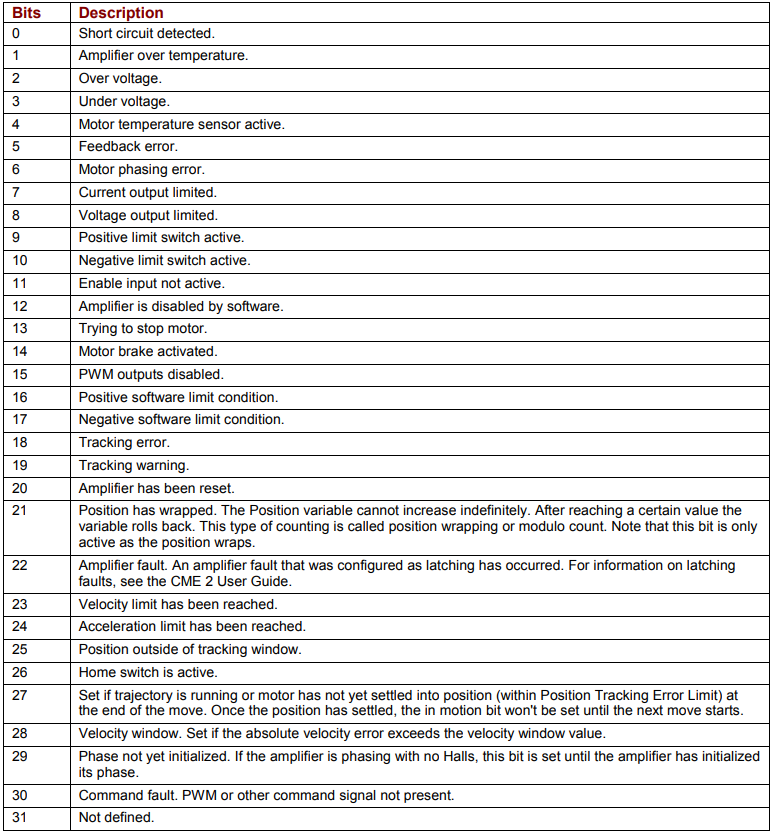
Status Register Variable (0xa0)
The status register variable (0xa0) provides amplifier status information. 0xa0 is read-only, and available in RAM only (not Flash). Bit mapped values described below:
| Bits | Description |
|---|---|
| 0 | Short circuit detected. |
| 1 | Amplifier over temperature. |
| 2 | Over voltage. |
| 3 | Under voltage. |
| 4 | Motor temperature sensor active. |
| 5 | Feedback error. |
| 6 | Motor phasing error. |
| 7 | Current output limited. |
| 8 | Voltage output limited. |
| 9 | Positive limit switch active. |
| 10 | Negative limit switch active. |
| 11 | Enable input not active. |
| 12 | Amplifier is disabled by software. |
| 13 | Trying to stop motor. |
| 14 | Motor brake activated. |
| 15 | PWM outputs disabled. |
| 16 | Positive software limit condition. |
| 17 | Negative software limit condition. |
| 18 | Tracking error. |
| 19 | Tracking warning. |
| 20 | Amplifier has been reset. |
| 21 | Position has wrapped. The Position variable cannot increase indefinitely. After reaching a certain value the variable rolls back. This type of counting is called position wrapping or modulo count. Note that this bit is only active as the position wraps. |
| 22 | Amplifier fault. An amplifier fault that was configured as latching has occurred. For information on latching faults, see the CME 2 User Guide. |
| 23 | Velocity limit has been reached. |
| 24 | Acceleration limit has been reached. |
| 25 | Position outside of tracking window. |
| 26 | Home switch is active. |
| 27 | Set if trajectory is running or motor has not yet settled into position (within Position Tracking Error Limit) at the end of the move. Once the position has settled, the in motion bit won’t be set until the next move starts. |
| 28 | Velocity window. Set if the absolute velocity error exceeds the velocity window value. |
| 29 | Phase not yet initialized. If the amplifier is phasing with no Halls, this bit is set until the amplifier has initialized its phase. |
| 30 | Command fault. PWM or other command signal not present. |
| 31 | Not defined. |
Original image of the table (from the PDF manual)
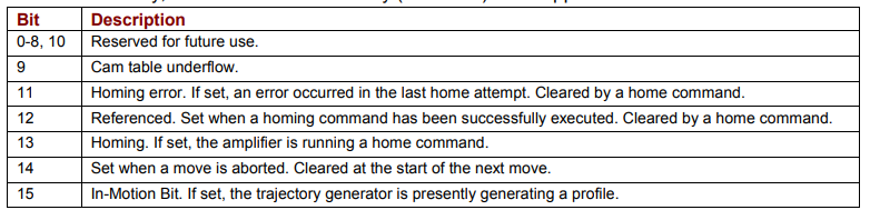
Trajectory Register Variable (0xc9)
The trajectory register variable (0xc9) provides trajectory generator status information. 0xc9 is read-only, and available in RAM only (not Flash). Bit mapped values described below:
| Bit | Description |
|---|---|
| 0-8, 10 | Reserved for future use. |
| 9 | Cam table underflow. |
| 11 | Homing error. If set, an error occurred in the last home attempt. Cleared by a home command. |
| 12 | Referenced. Set when a homing command has been successfully executed. Cleared by a home command. |
| 13 | Homing. If set, the amplifier is running a home command. |
| 14 | Set when a move is aborted. Cleared at the start of the next move. |
| 15 | In-Motion Bit. If set, the trajectory generator is presently generating a profile. |
Original image of the table (from the PDF manual)
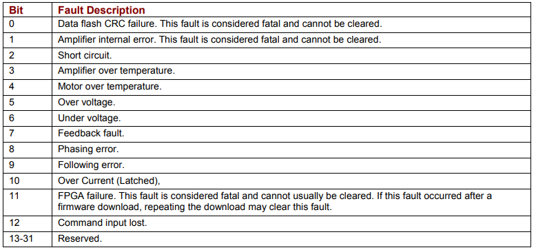
Fault Register Variable (0xa4)
The fault register variable (0xa4) shows latching faults that have occurred. 0xa4 is available in RAM only (not Flash).
Bit mapped values described below:
| Bit | Fault Description |
|---|---|
| 0 | Data flash CRC failure. This fault is considered fatal and cannot be cleared. |
| 1 | Amplifier internal error. This fault is considered fatal and cannot be cleared. |
| 2 | Short circuit. |
| 3 | Amplifier over temperature. |
| 4 | Motor over temperature. |
| 5 | Over voltage. |
| 6 | Under voltage. |
| 7 | Feedback fault. |
| 8 | Phasing error. |
| 9 | Following error. |
| 10 | Over Current (Latched). |
| 11 | FPGA failure. This fault is considered fatal and cannot usually be cleared. If this fault occurred after a firmware download, repeating the download may clear this fault. |
| 12 | Command input lost. |
| 13-31 | Reserved. |
Original image of the table (from the PDF manual)
Note that when a latching fault has occurred, bit 22 of the status register (0xa0) is set.
To clear a fault condition, write a 1 to the associated bit of the fault register (0xa4).
4.4 Reading Run Time Variables
This section describes the variables used to monitor run time conditions.
Current Loop Run Time Variables
| Variable ID | Bank | Description |
|---|---|---|
| 0x15 | R | Commanded current. Units: 0.01 A. |
| 0x0c | R | Actual current. Units: 0.01 A. |
| 0x25 | R | Limited current. Units: 0.01 A. |
Original image of the table (from the PDF manual)

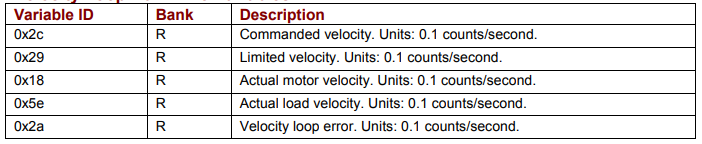
Velocity Loop Run Time Variables
| Variable ID | Bank | Description |
|---|---|---|
| 0x2c | R | Commanded velocity. Units: 0.1 counts/second. |
| 0x29 | R | Limited velocity. Units: 0.1 counts/second. |
| 0x18 | R | Actual motor velocity. Units: 0.1 counts/second. |
| 0x5e | R | Actual load velocity. Units: 0.1 counts/second. |
| 0x2a | R | Velocity loop error. Units: 0.1 counts/second. |
Original image of the table (from the PDF manual)
Position Loop Run Time Variables
| Variable ID | Bank | Description |
|---|---|---|
| 0x32 | R | Motor position. Units: counts. |
| 0x17 | R | Load position. Units: counts. |
| 0x35 | R | Following Error. Units: counts. |
Original image of the table (from the PDF manual)

Position Loop Inputs from the Trajectory Generator (Variables)
| Variable ID | Bank | Description |
|---|---|---|
| 0x3d | R | Commanded position. Units: counts. |
| 0x2d | R | Limited position. Units: counts. |
| 0x3b | R | Profile velocity. Units: 0.1 counts/second. |
| 0x3c | R | Profile acceleration. Units: 10 counts/second². |
Original image of the table (from the PDF manual)

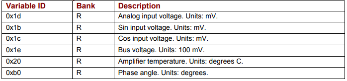
Miscellaneous System Variables
| Variable ID | Bank | Description |
|---|---|---|
| 0x1d | R | Analog input voltage. Units: mV. |
| 0x1b | R | Sin input voltage. Units: mV. |
| 0x1c | R | Cos input voltage. Units: mV. |
| 0x1e | R | Bus voltage. Units: 100 mV. |
| 0x20 | R | Amplifier temperature. Units: degrees C. |
| 0xb0 | R | Phase angle. Units: degrees. |
Original image of the table (from the PDF manual)
4.5 Reading Digital Inputs
Input States Variable (0xa6)
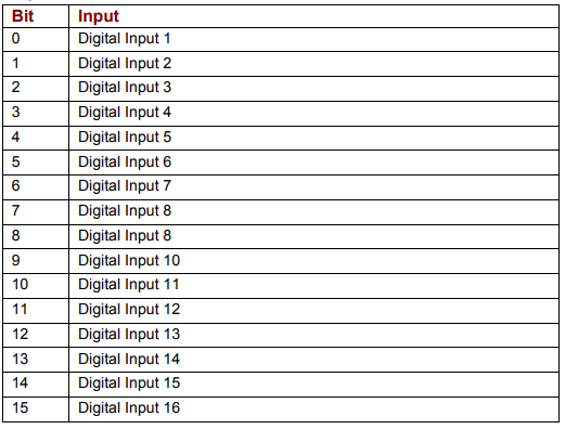
The high/low states of the amplifier’s programmable digital inputs can be read using variable 0xa6. Each bit represents an input number as shown below. If an input is high, the corresponding bit is set to 1. If the input is low, the corresponding bit is set to 0.
For instance, if the value of 0xa6 is 33, the binary equivalent is 100001, showing that IN1 and IN6 are high and the other inputs are low.
0xa6 is read-only, and available in RAM only (not Flash). Bit mapped values described below.
NOTE: The number of programmable digital inputs varies depending on amplifier model. See the amplifier documentation.
Digital inputs – bit mapping
| Bit | Input |
|---|---|
| 0 | Digital Input 1 |
| 1 | Digital Input 2 |
| 2 | Digital Input 3 |
| 3 | Digital Input 4 |
| 4 | Digital Input 5 |
| 5 | Digital Input 6 |
| 6 | Digital Input 7 |
| 7 | Digital Input 8 |
| 8 | Digital Input 9 (the source table shows "Digital Input 8" – a typo) |
| 9 | Digital Input 10 |
| 10 | Digital Input 11 |
| 11 | Digital Input 12 |
| 12 | Digital Input 13 |
| 13 | Digital Input 14 |
| 14 | Digital Input 15 |
| 15 | Digital Input 16 |
Original image of the table (from the PDF manual)
4.6 Reading/Setting Digital Outputs
The amplifiers digital outputs can be programmed by CME 2 to reflect the state of any one or more of the amplifier’s event status register bits. The outputs can also be configured so their state can be set by the controller program.
The external controller, through the Output State variable, can set an output inactive or active. The actual level of the output pin however is determined by the Output Configuration variable. This variable sets the actual output pin to be high or low when active. When the amplifier powers up or is reset, all outputs are initially inactive. To ensure that outputs are high, or off, after power up or reset, they should be configured as active low.
Configuring Outputs (0x70 – 0x77)
Before a controller program can set an output pin’s active/inactive state, the output must be configured for program control. This is done by setting the appropriate bits in the output’s configuration variable.
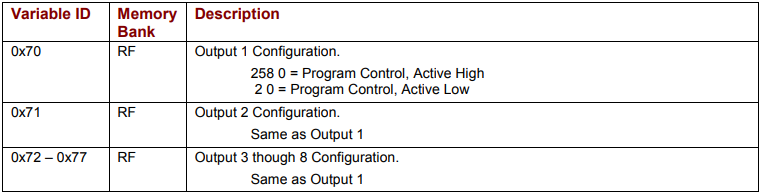
The output configuration variables start with 0x70 for Output 1 and run to 0x77 for Output 8, as described below. These variables require two values be sent with Set (s) command.
NOTE: The number of programmable digital inputs varies depending on amplifier mode. See the amplifier documentation
Output configuration variables
| Variable ID | Memory Bank | Description |
|---|---|---|
| 0x70 | RF | Output 1 Configuration: 258 0 = Program Control, Active High; 2 0 = Program Control, Active Low. |
| 0x71 | RF | Output 2 Configuration. Same as Output 1. |
| 0x72 – 0x77 | RF | Output 3 through 8 Configuration. Same as Output 1. |
Original image of the table (from the PDF manual)
Setting Output States (0xab)
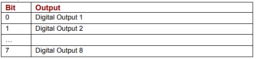
Writing the variable 0xab sets the active/inactive states of digital outputs that have been configured for program control. Each bit represents an output number as shown below. A bit value of 1 corresponds to an active output. A bit value of 0 corresponds to an inactive output.
Writing a 1 or 0 to an output that has not been configured for program control will have no effect on the output.
NOTE: The number of programmable digital outputs varies depending on amplifier model. See the amplifier documentation.
Digital outputs – bit mapping
| Bit | Output |
|---|---|
| 0 | Digital Output 1 |
| 1 | Digital Output 2 |
| … | … |
| 7 | Digital Output 8 |
Original image of the table (from the PDF manual)
Reading Output States (0xab)
Reading 0xab gets the active/inactive states of all the amplifier’s digital outputs, including those which are not set to program control.
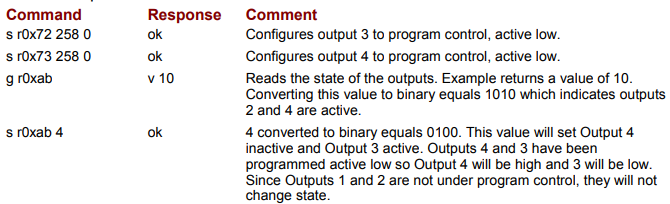
Reading/Setting Output Example
The controller configures 2 outputs for program control, reads the state of the outputs, and then sets an output low.
| Command | Response | Comment |
|---|---|---|
| s r0x72 258 0 | ok | Configures output 3 to program control, active low. |
| s r0x73 258 0 | ok | Configures output 4 to program control, active low. |
| g r0xab | v 10 | Reads the state of the outputs. Example returns a value of 10. Converting this value to binary equals 1010 which indicates outputs 2 and 4 are active. |
| s r0xab 4 | ok | 4 converted to binary equals 0100. This value will set Output 4 inactive and Output 3 active. Outputs 4 and 3 have been programmed active low so Output 4 will be high and 3 will be low. Since Outputs 1 and 2 are not under program control, they will not change state. |
Original image of the table (from the PDF manual)
Słowa kluczowe
baud rate, prędkość transmisji, limity prądu, peak current, I2T, wzmocnienia pętli, Cp, Ci, Vp, Vi, Pp, Vff, Aff, filtry, rejestr statusu, 0xa0, 0xc9, rejestr błędów, 0xa4, zmienne bieżące, wejścia cyfrowe, 0xa6, wyjścia cyfrowe, 0xab, 0x70