
11. Control Loops – Velocity Loop
Streszczenie: Pętla prędkości: podstawowe ustawienia i ręczne strojenie, uwagi o trybie prędkościowym – schemat, wejścia, limity prędkości i przyspieszeń (z opisem diagramu), wzmocnienia Vp/Vi, przesunięcie wzmocnień, filtry polecenia i wyjścia.
EN: Control loops, part 2: velocity loop setup and tuning, limits, gains, gains shift and filters.
Dotyczy: program CME 2 do konfiguracji i strojenia serwonapędów oraz napędów krokowych Copley Controls (m.in. Xenus, Accelnet, Stepnet, Accelus, Junus)
Źródło: dokumentacja producenta (Copley Controls CME 2 User Guide); tabele przepisane z obrazów na tekst, opisy diagramów – opracowanie Multiprojekt
Rozdział 11 „Control Loops” podzielono na 3 strony: Current Loop · Velocity Loop · Position Loop and Auto Tune.
11.4 Velocity Loop Setup and Tuning
Initial velocity loop proportional gain (Vp) and velocity loop integral gain (Vi) values can be calculated with The Calculate Function (p. 46).
Enter basic Velocity Loop settings
1.  Click V Loop (screen contents vary with model and configuration):
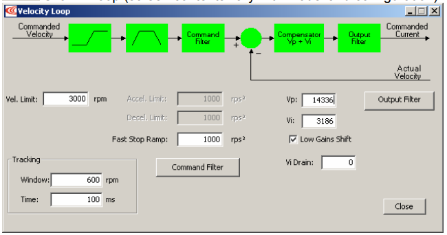
2. Change/verify Velocity Loop parameters as needed.
Velocity Loop – parameters
| Parameter | Description |
|---|---|
| Velocity Limit | Top speed limit. Max value may depend upon the back EMF & the Encoder value. Min value: 0. |
| Acceleration Limit | Maximum acceleration rate. Max value may depend upon load, inertia, & peak current. Min value: 1. (Does not apply in position mode.) |
| Deceleration Limit | Maximum deceleration rate. Max value may depend upon load, inertia, & peak current. Min value: 1. (Does not apply in position mode.) |
| Tracking Window | See Tracking Window Details. |
| Tracking Time | See Tracking Window Details. |
| Vp | Velocity loop proportional gain. Range: 0 to 32,767. |
| Vi | Velocity loop integral gain. Range: 0 to 32,767. |
| Fast Stop Ramp | Deceleration rate used by the velocity loop when the amplifier is hardware disabled. Range: 0 to 100,000,000. Default: velocity loop Decel. Limit value. For more information, see Velocity Loop Limits. |
| Low Gains Shift | Increases the resolution of the units used to express Vp and Vi, providing more precise tuning. For more information, see Velocity Gains Shift. |
| Hi Gains Shift | Decreases the resolution of the units used to express Vp and Vi, providing more precise tuning. For more information, see Velocity Gains Shift. |
| Vi Drain (integral bleed) | Vi drain modifies the effect of velocity loop integral gain. The higher the Vi Drain value, the faster the integral sum is lowered. Range: 0 to 32,000. Default: 0. |
| Command Filter | Programmable command input filter. Disabled by default. See Velocity Loop Command and Output Filters. |
| Output Filter | Programmable output filter. Default filter type: Low-Pass, 2-pole Butterworth (Cut Off Frequency 200 Hz). See Velocity Loop Command and Output Filters. |
3. Click Close to close screen.
Manually Tune the Velocity Loop
METHOD: Apply square-wave excitation to velocity loop and adjust proportional gain (Vp) and integral gain (Vi) to obtain desired waveform. For instance:
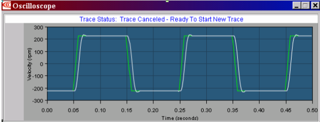
NOTE: During tuning, observe any warnings that appear to the left of the trace
1 Click the Scope Tool.
2.  Choose Velocity from the Function Generator Apply To: list.
3.  On the Settings tab, make sure Auto Setup is selected. Auto Setup automatically sets the following parameters:
Scope settings for velocity loop tuning
| Parameter | Description |
|---|---|
| Function Generator Tab | |
| Function | Square Wave. |
| Amplitude | 10% of maximum velocity value. |
| Frequency | 5 Hz. |
| Settings Tab | |
| Channel 1 | Limited velocity (green). |
| Channel 2 | Actual Motor Velocity (white). |
4.  Verify that Amplitude value is not excessive for the motor.
5.  Click Start.
6. On the Gains tab, adjust velocity loop proportional gain (Vp):
Set velocity loop integral gain (Vi) to zero.
Raise or lower proportional gain (Vp) to obtain desired step response. (Typically, little or no overshoot on a 5 Hz small, slow-speed square wave.)
7. Adjust velocity loop integral gain (Vi) until desired settling time is obtained.
8.  Press Stop to stop the function generator.
9.  On the Main screen, click Save to Flash to avoid losing the changes
11.5 Notes on the Velocity Mode and Velocity Loop
11.5.1 Velocity Loop Diagram
As shown below, the velocity loop limiting stage accepts a velocity command, applies limits, and passes a limited velocity command to the input filter. The filter then passes a velocity command to the summing junction. The summing junction subtracts the actual velocity, represented by the feedback signal, and produces an error signal. (The velocity loop feedback signal is always from the motor feedback device even when an additional encoder is attached to the load.) The error signal is then processed using the integral and proportional gains to produce a current command. Programmable digital filters are provided on both the input and output command signals.
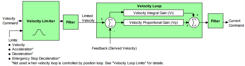
11.5.2 Inputs
In velocity mode, the velocity command comes from one of the following:
- The amplifier’s analog or PWM inputs.
- A CANopen network via the amplifier’s CAN interface.
- A Copley Virtual Motion (CVM) control program.
- The amplifier’s internal function generator.
In position mode, the velocity command is generated by the position loop.
11.5.3 Velocity Loop Limits
The velocity command is limited based on the following set of parameters designed to protect the motor and/or the mechanical system.
Velocity loop limiters
| Limiter | Description |
|---|---|
| Velocity Limit | Sets the maximum velocity command input to the velocity loop. |
| Acceleration Limit | Limits the maximum acceleration rate of the commanded velocity input to the velocity loop. This limit is used in velocity mode only. In position mode, the trajectory generator handles acceleration limiting. |
| Deceleration Limit | Limits the maximum deceleration rate of the commanded velocity input to the velocity loop. This limit is used in velocity mode only. In position mode, the trajectory generator handles deceleration limiting. |
| Fast Stop Ramp | Specifies the deceleration rate used by the velocity loop when the amplifier is hardware disabled. (Fast stop ramp is not used when amplifier is software disabled.) If the brake output is active, the fast stop ramp is used to decelerate the motor before applying the brake. Note that Fast Stop Ramp is used only in velocity mode. In position mode, the trajectory generator handles controlled stopping of the motor. There is one exception: if a non-latched following error occurs in position mode, then the amplifier drops into velocity mode and the Fast Stop Ramp is used. For more information, see Following Error Fault Details. |
11.5.4 Diagram: Effects of Limits on Velocity Command
The following diagram illustrates the effects of the velocity loop limits.
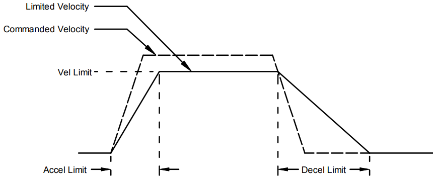
Diagram description (text version): Effect of the velocity loop limits: the Commanded Velocity (dashed) rises steeply, exceeds the Vel Limit and drops steeply. The Limited Velocity (solid) rises no faster than the Accel Limit, is clipped at the Vel Limit, and falls no faster than the Decel Limit, so it reaches zero later than the command.
11.5.5 Velocity Loop Gains
The velocity loop uses these gains:
Velocity loop gains
| Gain | Description |
|---|---|
| Vp - Velocity loop proportional | The velocity error (the difference between the actual and the limited commanded velocity) is multiplied by this gain. The primary effect of this gain is to increase bandwidth (or decrease the step-response time) as the gain is increased. |
| Vi - Velocity loop integral | The integral of the velocity error is multiplied by this value. Integral gain reduces the velocity error to zero over time. It controls the DC accuracy of the loop, or the flatness of the top of a square wave signal. The error integral is the accumulated sum of the velocity error value over time. |
11.5.6 Velocity Gains Shift
The Velocity Gains Shift feature adjusts the resolution of the units used to express Vp and Vi, providing more precise tuning. If the non-scaled value of Vp or Vi is 64 or less, the Low Gains Shift option is available to increase the gains adjustment resolution. (Such low values are likely to be called for when tuning a linear motor with an encoder resolution finer than a micrometer.) If the non-scaled value of Vp or Vi is 24001 or higher, the High Gains Shift option is available to decrease the gains adjustment resolution.
11.5.7 Velocity Loop Command and Output Filters
The velocity loop contains two programmable digital filters. The input filter should be used to reduce the effects of a noisy velocity command signal. The output filter can be used to reduce the excitation of any resonance in the motion system. Two filter classes can be programmed: the Low-Pass and the Custom Bi-Quadratic. The Low-Pass filter class includes the Single-Pole and the Two-Pole Butterworth filter types. The Custom Bi-Quadratic filter allows advanced users to define their own filters incorporating two poles and two zeros.
For more information, see Low-Pass and Bi-Quad Filters.
11.5.8 Velocity Loop Outputs
The output of the velocity loop is a current command used as the input to the current loop.
Słowa kluczowe
pętla prędkości, strojenie, Vp, Vi, limit prędkości, przyspieszenie, hamowanie, velocity gains shift, filtr, Scope