
14. Control Panel
Streszczenie: Panel sterowania (Control Panel): wskaźniki i komunikaty stanu, kanały monitorowania, funkcje sterujące (enable/disable, kasowanie błędów, zerowanie pozycji) oraz ruch w trybie jog.
EN: Control Panel: status indicators, monitor channels, control functions and jog mode.
Dotyczy: program CME 2 do konfiguracji i strojenia serwonapędów oraz napędów krokowych Copley Controls (m.in. Xenus, Accelnet, Stepnet, Accelus, Junus)
Źródło: dokumentacja producenta (Copley Controls CME 2 User Guide); tabele przepisane z obrazów na tekst – opracowanie Multiprojekt
Become familiar with the CME 2 Control Panel and its functions. Perform the steps outlined below to access the panel and its functions. Details follow in chapter.1
1.  Click to open the Control Panel:
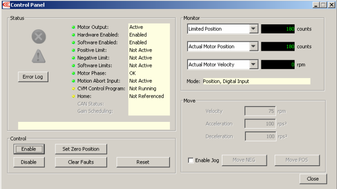
22. See this chapter for a Control Panel Overview and details on:
- Status Indicators and Messages
- Control Panel Monitor Channels
- Control Functions
- Jog Mode
14.1:1 Control Panel Overview
Each of the Control Panel features labeled below is described in the following sections
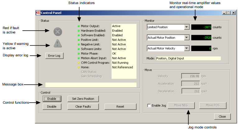
14.2:2 Status Indicators and Messages
The Status area includes status indicator lights (described below) and a message box. Any red lights indicate that motion will be inhibited.
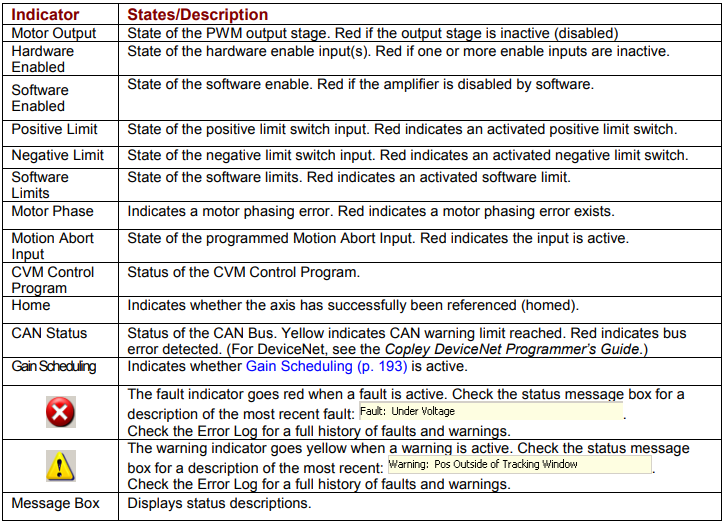
Control Panel – status indicators
| Indicator | States/Description |
|---|---|
| Motor Output | State of the PWM output stage. Red if the output stage is inactive (disabled). |
| Hardware Enabled | State of the hardware enable input(s). Red if one or more enable inputs are inactive. |
| Software Enabled | State of the software enable. Red if the amplifier is disabled by software. |
| Positive Limit | State of the positive limit switch input. Red indicates an activated positive limit switch. |
| Negative Limit | State of the negative limit switch input. Red indicates an activated negative limit switch. |
| Software Limits | State of the software limits. Red indicates an activated software limit. |
| Motor Phase | Indicates a motor phasing error. Red indicates a motor phasing error exists. |
| Motion Abort Input | State of the programmed Motion Abort Input. Red indicates the input is active. |
| CVM Control Program | Status of the CVM Control Program. |
| Home | Indicates whether the axis has successfully been referenced (homed). |
| CAN Status | Status of the CAN Bus. Yellow indicates CAN warning limit reached. Red indicates bus error detected. (For DeviceNet, see the Copley DeviceNet Programmer’s Guide.) |
| Gain Scheduling | Indicates whether Gain Scheduling is active. |
| Fault indicator (red X) | The fault indicator goes red when a fault is active. Check the status message box for a description of the most recent fault (e.g. “Fault: Under Voltage”). Check the Error Log for a full history of faults and warnings. |
| Warning indicator (yellow !) | The warning indicator goes yellow when a warning is active. Check the status message box for a description of the most recent warning (e.g. “Warning: Pos Outside of Tracking Window”). Check the Error Log for a full history of faults and warnings. |
| Message Box | Displays status descriptions. |
14.3:3 Control Panel Monitor Channels
The Control Panel Monitor channels can display real-time values on up to three separate variables. The procedure follows.
Set up a monitor display channel
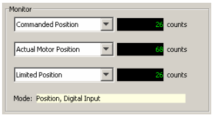
Click in the list box and select a variable from the list. Disabled disables the display. Other options represent the following amplifier values:
•
- Actual Current • Following Error • Passive Load Position
• - Actual Motor Velocity • Commanded Current • Limited Position
• - Actual Motor Position • Commanded Velocity • Analog Command
• - Actual Load Velocity • Commanded Position • Bus Voltage
• - Actual Load Position • Profile Velocity • Amplifier Temperature
• - Velocity Error • Profile Acceleration • Motor Phase Angle
Mode: Displays the amplifier’s present operating mode. In camming it also
displays the active cam table number.
14.4:4 Control Functions
The Control area of the screen provides functions related to overall amplifier control. The screen options vary with model and configuration.
Use the Control Panel Control Functions
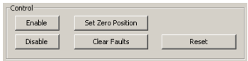
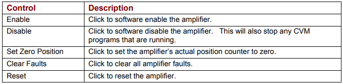
Control the operational state of the amplifier using the buttons as described below.
| Control | Description |
|---|---|
| Enable | Click to software enable the amplifier. |
| Disable | Click to software disable the amplifier. This will also stop any CVM programs that are running. |
| Set Zero Position | Click to set the amplifier’s actual position counter to zero. |
| Clear Faults | Click to clear all amplifier faults. |
| Reset | Click to reset the amplifier. |
WARNING: Risk of unexpected or uncontrolled motion.

motion
Using the CME 2 Set Zero Position function while the amplifier is operating under external control could cause unexpected or uncontrolled motion.
Failure to heed this warning can cause equipment damage.
14.5:5 Jog Mode
Jog mode provides a simple means for generating forward or reverse commands, as shown in the procedure below.
Run a move in jog mode
1.1 To put the amplifier in jog mode, set the Enable Jog option.2
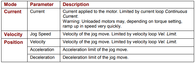
2. Set up a jog move by setting the following mode-specific parameters:
| Mode | Parameter | Description |
|---|---|---|
| Current | Current | Current applied to the motor. Limited by current loop Continuous Current. Warning: Unloaded motors may, depending on torque setting, ramp up in speed very quickly. |
| Velocity | Jog Speed | Velocity of the jog move. Limited by velocity loop Vel. Limit. |
| Position | Velocity | Velocity of the jog move. Limited by velocity loop Vel. Limit. |
| Position | Acceleration | Acceleration limit of the jog move. |
| Position | Deceleration | Deceleration limit of the jog move. |
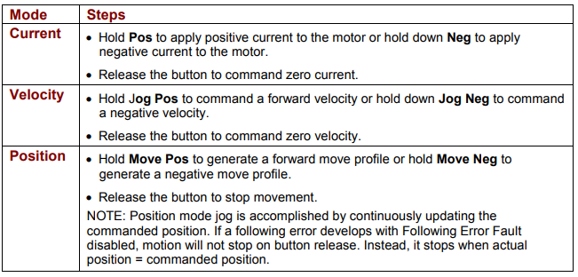
33. Command the move:
| Mode | Steps |
|---|---|
| Current | Hold Pos to apply positive current to the motor or hold down Neg to apply negative current to the motor. Release the button to command zero current. |
| Velocity | Hold Jog Pos to command a forward velocity or hold down Jog Neg to command a negative velocity. Release the button to command zero velocity. |
| Position | Hold Move Pos to generate a forward move profile or hold Move Neg to generate a negative move profile. Release the button to stop movement. NOTE: Position mode jog is accomplished by continuously updating the commanded position. If a following error develops with Following Error Fault disabled, motion will not stop on button release. Instead, it stops when actual position = commanded position. |
Słowa kluczowe
Control Panel, wskaźniki stanu, monitor, jog, enable, disable, kasowanie błędów, zerowanie pozycji