
Appendix B: Amplifier and Related Objects (B.11–B.13) – status, events, faults, digital I/O, enable/disable
Streszczenie: Obiekt AmpObj, część 2: rejestry statusu, zdarzeń i błędów (CML_EVENT_STATUS, CML_AMP_EVENT, CML_AMP_FAULT, FaultMask, ClearFaults), wejścia i wyjścia cyfrowe (debounce, konfiguracja wejść CML_INPUT_PIN_CONFIG, konfiguracja wyjść CML_OUTPUT_PIN_CONFIG z parametrami) oraz włączanie i wyłączanie napędu.
EN: Amplifier object part 2: status, event and fault registers, digital inputs and outputs, enable/disable.
Dotyczy: Copley Motion Objects (CMO, biblioteka COM CMLCOMLib) – sterowanie serwonapędami Copley CANopen z PC (Windows; VB 6.0, VB .NET, LabVIEW)
Źródło: dokumentacja producenta (Copley Motion Objects Programmer’s Guide); tabele przepisane z obrazów na tekst – opracowanie Multiprojekt
B.11 Status, Events, and Faults
Amplifier status and fault information can be accessed using the following methods and properties of CMLCOMLib.AmpObj.
B.11.1 Amplifier Status Register Methods
These methods read the amplifier’s status registers (CML_EVENT_STATUS).
| Member | Description |
|---|---|
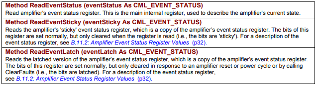
Method ReadEventStatus (eventStatus As CML_EVENT_STATUS) | Read amplifier's event status register. This is the main internal register, used to describe the amplifier’s current state. |
Method ReadEventSticky (eventSticky As CML_EVENT_STATUS) | Reads the amplifier's 'sticky' event status register, which is a copy of the amplifier's event status register. The bits of this register are set normally, but only cleared when the register is read (i.e., the bits are 'sticky'). For a description of the event status register, see B.11.2: Amplifier Event Status Register Values. |
Method ReadEventLatch (eventLatch As CML_EVENT_STATUS) | Reads the latched version of the amplifier’s event status register, which is a copy of the amplifier’s event status register. The bits of this register are set normally, but only cleared in response to an amplifier reset or power cycle or by calling ClearFaults (i.e., the bits are latched). For a description of the event status register, see B.11.2: Amplifier Event Status Register Values. |
Original image of the table (from the PDF manual)
B.11.2 Amplifier Event Status Register Values
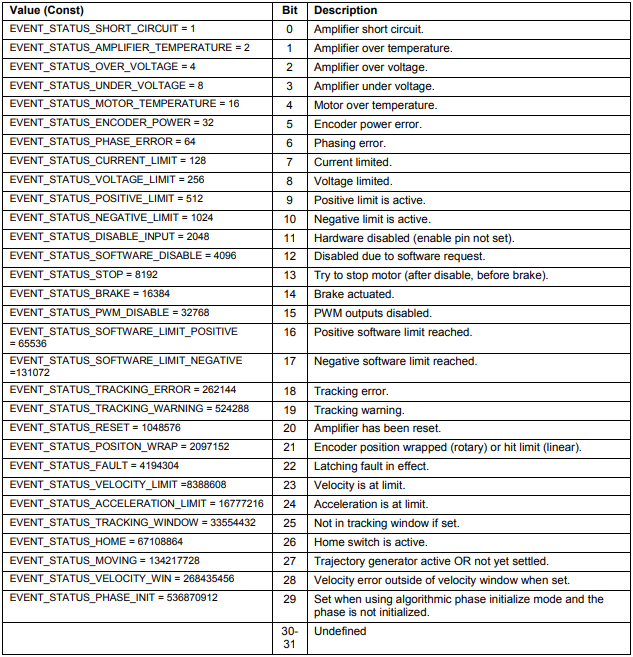
Bits in the Event Status register describes various amplifier status conditions, as described below.
Amplifier Event Status Register Values (CML_EVENT_STATUS)
| Value (Const) | Bit | Description |
|---|---|---|
| EVENT_STATUS_SHORT_CIRCUIT = 1 | 0 | Amplifier short circuit. |
| EVENT_STATUS_AMPLIFIER_TEMPERATURE = 2 | 1 | Amplifier over temperature. |
| EVENT_STATUS_OVER_VOLTAGE = 4 | 2 | Amplifier over voltage. |
| EVENT_STATUS_UNDER_VOLTAGE = 8 | 3 | Amplifier under voltage. |
| EVENT_STATUS_MOTOR_TEMPERATURE = 16 | 4 | Motor over temperature. |
| EVENT_STATUS_ENCODER_POWER = 32 | 5 | Encoder power error. |
| EVENT_STATUS_PHASE_ERROR = 64 | 6 | Phasing error. |
| EVENT_STATUS_CURRENT_LIMIT = 128 | 7 | Current limited. |
| EVENT_STATUS_VOLTAGE_LIMIT = 256 | 8 | Voltage limited. |
| EVENT_STATUS_POSITIVE_LIMIT = 512 | 9 | Positive limit is active. |
| EVENT_STATUS_NEGATIVE_LIMIT = 1024 | 10 | Negative limit is active. |
| EVENT_STATUS_DISABLE_INPUT = 2048 | 11 | Hardware disabled (enable pin not set). |
| EVENT_STATUS_SOFTWARE_DISABLE = 4096 | 12 | Disabled due to software request. |
| EVENT_STATUS_STOP = 8192 | 13 | Try to stop motor (after disable, before brake). |
| EVENT_STATUS_BRAKE = 16384 | 14 | Brake actuated. |
| EVENT_STATUS_PWM_DISABLE = 32768 | 15 | PWM outputs disabled. |
| EVENT_STATUS_SOFTWARE_LIMIT_POSITIVE = 65536 | 16 | Positive software limit reached. |
| EVENT_STATUS_SOFTWARE_LIMIT_NEGATIVE = 131072 | 17 | Negative software limit reached. |
| EVENT_STATUS_TRACKING_ERROR = 262144 | 18 | Tracking error. |
| EVENT_STATUS_TRACKING_WARNING = 524288 | 19 | Tracking warning. |
| EVENT_STATUS_RESET = 1048576 | 20 | Amplifier has been reset. |
| EVENT_STATUS_POSITON_WRAP = 2097152 | 21 | Encoder position wrapped (rotary) or hit limit (linear). |
| EVENT_STATUS_FAULT = 4194304 | 22 | Latching fault in effect. |
| EVENT_STATUS_VELOCITY_LIMIT = 8388608 | 23 | Velocity is at limit. |
| EVENT_STATUS_ACCELERATION_LIMIT = 16777216 | 24 | Acceleration is at limit. |
| EVENT_STATUS_TRACKING_WINDOW = 33554432 | 25 | Not in tracking window if set. |
| EVENT_STATUS_HOME = 67108864 | 26 | Home switch is active. |
| EVENT_STATUS_MOVING = 134217728 | 27 | Trajectory generator active OR not yet settled. |
| EVENT_STATUS_VELOCITY_WIN = 268435456 | 28 | Velocity error outside of velocity window when set. |
| EVENT_STATUS_PHASE_INIT = 536870912 | 29 | Set when using algorithmic phase initialize mode and the phase is not initialized. |
| 30-31 | Undefined |
Original image of the table (from the PDF manual)
B.11.3 Amplifier Event Register Methods
The following member of CMLCOMLib.AmpObj is used to read the amplifier’s event register
Method ReadEventMask (eventMask As CML_AMP_EVENT)
Reads the current state of the amplifier’s event register. The event mask is a bit-mapped variable that describes the state of the amplifier. The contents of this variable are built up from several different amplifier status words. For a description of masking, see G.1: Masking. Event values are described below.
B.11.4 Amplifier Event Register Values
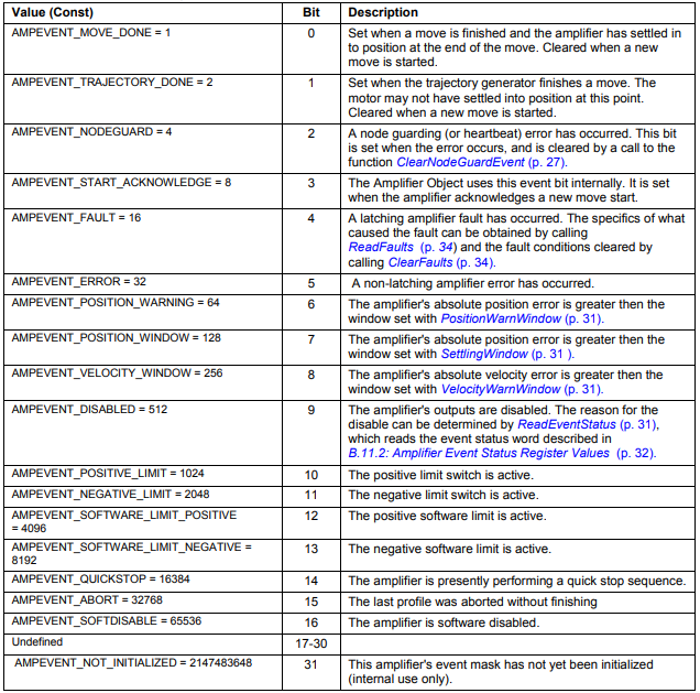
Bits in the Amp Event register describes various amplifier states, as described below.
Amplifier event values (CML_AMP_EVENT)
| Value (Const) | Bit | Description |
|---|---|---|
| AMPEVENT_MOVE_DONE = 1 | 0 | Set when a move is finished and the amplifier has settled in to position at the end of the move. Cleared when a new move is started. |
| AMPEVENT_TRAJECTORY_DONE = 2 | 1 | Set when the trajectory generator finishes a move. The motor may not have settled into position at this point. Cleared when a new move is started. |
| AMPEVENT_NODEGUARD = 4 | 2 | A node guarding (or heartbeat) error has occurred. This bit is set when the error occurs, and is cleared by a call to the function ClearNodeGuardEvent. |
| AMPEVENT_START_ACKNOWLEDGE = 8 | 3 | The Amplifier Object uses this event bit internally. It is set when the amplifier acknowledges a new move start. |
| AMPEVENT_FAULT = 16 | 4 | A latching amplifier fault has occurred. The specifics of what caused the fault can be obtained by calling ReadFaults and the fault conditions cleared by calling ClearFaults. |
| AMPEVENT_ERROR = 32 | 5 | A non-latching amplifier error has occurred. |
| AMPEVENT_POSITION_WARNING = 64 | 6 | The amplifier's absolute position error is greater then the window set with PositionWarnWindow. |
| AMPEVENT_POSITION_WINDOW = 128 | 7 | The amplifier's absolute position error is greater then the window set with SettlingWindow. |
| AMPEVENT_VELOCITY_WINDOW = 256 | 8 | The amplifier's absolute velocity error is greater then the window set with VelocityWarnWindow. |
| AMPEVENT_DISABLED = 512 | 9 | The amplifier's outputs are disabled. The reason for the disable can be determined by ReadEventStatus, which reads the event status word described in B.11.2: Amplifier Event Status Register Values. |
| AMPEVENT_POSITIVE_LIMIT = 1024 | 10 | The positive limit switch is active. |
| AMPEVENT_NEGATIVE_LIMIT = 2048 | 11 | The negative limit switch is active. |
| AMPEVENT_SOFTWARE_LIMIT_POSITIVE = 4096 | 12 | The positive software limit is active. |
| AMPEVENT_SOFTWARE_LIMIT_NEGATIVE = 8192 | 13 | The negative software limit is active. |
| AMPEVENT_QUICKSTOP = 16384 | 14 | The amplifier is presently performing a quick stop sequence. |
| AMPEVENT_ABORT = 32768 | 15 | The last profile was aborted without finishing. |
| AMPEVENT_SOFTDISABLE = 65536 | 16 | The amplifier is software disabled. |
| Undefined | 17-30 | |
| AMPEVENT_NOT_INITIALIZED = 2147483648 | 31 | This amplifier's event mask has not yet been initialized (internal use only). |
Original image of the table (from the PDF manual)
B.11.5 Amplifier Faults Methods and Properties
These methods and properties, members of CMLCOMLib.AmpObj, are associated with amplifier faults.
| Member | Description |
|---|---|
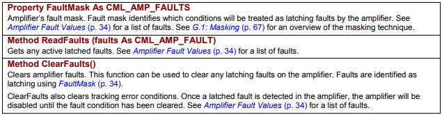
Property FaultMask As CML_AMP_FAULTS | Amplifier’s fault mask. Fault mask identifies which conditions will be treated as latching faults by the amplifier. See Amplifier Fault Values for a list of faults. See G.1: Masking for an overview of the masking technique. |
Method ReadFaults (faults As CML_AMP_FAULT) | Gets any active latched faults. See Amplifier Fault Values for a list of faults. |
Method ClearFaults() | Clears amplifier faults. This function can be used to clear any latching faults on the amplifier. Faults are identified as latching using FaultMask. ClearFaults also clears tracking error conditions. Once a latched fault is detected in the amplifier, the amplifier will be disabled until the fault condition has been cleared. See Amplifier Fault Values for a list of faults. |
Original image of the table (from the PDF manual)
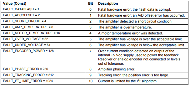
B.11.6 Amplifier Fault Values
Bits in the Amp Faults register describes various amplifier faults, as described below
Amplifier Fault Values (CML_AMP_FAULT)
| Value (Const) | Bit | Description |
|---|---|---|
| FAULT_DATAFLASH = 1 | 0 | Fatal hardware error: the flash data is corrupt. |
| FAULT_ADCOFFSET = 2 | 1 | Fatal hardware error: an A/D offset error has occurred. |
| FAULT_SHORT_CIRCUIT = 4 | 2 | The amplifier detected a short circuit condition. |
| FAULT_AMP_TEMPERATURE = 8 | 3 | The amplifier is over temperature. |
| FAULT_MOTOR_TEMPERATURE = 16 | 4 | A motor temperature error was detected. |
| FAULT_OVER_VOLTAGE = 32 | 5 | The amplifier bus voltage is over the acceptable limit. |
| FAULT_UNDER_VOLTAGE = 64 | 6 | The amplifier bus voltage is below the acceptable limit. |
| FAULT_ENCODER_POWER = 128 | 7 | Over current condition detected on output of the internal +5 Vdc supply used to power the feedback. Resolver or analog encoder not connected or levels out of tolerance. |
| FAULT_PHASE_ERROR = 256 | 8 | Amplifier phasing error. |
| FAULT_TRACKING_ERROR = 512 | 9 | Tracking error, the position error is too large. |
| FAULT_I²T_LIMIT_ERROR = 1024 | 10 | Current is limited by the I²T algorithm. |
Original image of the table (from the PDF manual)
B.12 Amplifier Digital Inputs/Outputs
Amplifier digital inputs/outputs are managed by these CMLCOMLib.AmpObj properties/methods.
B.12.1 Input Pin Methods
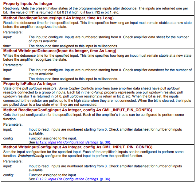
Each of the amplifier’s digital inputs can be configured to perform an action. Note that one input can perform the same action as another (for instance, two hardware disable inputs). The methods below, members of CMLCOMLib.AmpObj, relate to the states and configuration of the inputs.
| Member | Description |
|---|---|
Property Inputs As Integer | Read-only. Gets the present hi/low states of the programmable inputs after debounce. The inputs are returned one per bit. The value of IN1 is returned in bit 0 (1 if high, 0 if low), IN2 in bit 1, etc. |
Method ReadInputDebouce(input As Integer, time As Long) | Reads the debounce time for the specified input. This time specifies how long an input must remain stable at a new state before the amplifier recognizes the state. Parameters: input – the input to configure; inputs are numbered starting from 0 (check amplifier data sheet for the number of inputs available); time – the debounce time assigned to this input in milliseconds. |
Method WriteInputDebounce(input As Integer, time As Long) | Writes the debounce time for the specified input. This time specifies how long an input must remain stable at a new state before the amplifier recognizes the state. Parameters: input – the input to configure; inputs are numbered starting from 0 (check amplifier datasheet for the number of inputs available); time – the debounce time assigned to this input in milliseconds. |
Property IoPullup As Integer | State of the pull up/down resistors. Some Copley Controls amplifiers (see amplifier data sheet) have pull up/down resistors connected to a group of inputs. Each bit in the IoPullup property represents one pull up/down resistor; pull up/down resistor 1 is returned in bit 0, pull up/down resistor 2 is return in bit 2, etc. When the bit is set, the inputs connected to the resistor are pulled up to the high state when they are not connected. When the bit is cleared, the inputs are pulled down to a low state when they are not connected. |
Method ReadInputConfig(input As Integer, config As CML_INPUT_PIN_CONFIG) | Gets the input configuration for the specified input. Each of the amplifier’s inputs can be configured to perform some function. Parameters: input – input to read; inputs are numbered starting from 0 (check amplifier datasheet for number of inputs available); config – function assigned to the input, see B.12.2: Input Pin Configuration Settings. |
Method WriteInputConfig(input As Integer, config As CML_INPUT_PIN_CONFIG) | Sets the input configuration for the specified input. Each of the amplifier’s inputs can be configured to perform some function. WriteInputConfig configures the specified input to perform the specified function. Parameters: input – input to read; inputs are numbered starting from 0 (check amplifier datasheet for number of inputs available); config – function assigned to the input, see B.12.2: Input Pin Configuration Settings. |
Original image of the table (from the PDF manual)
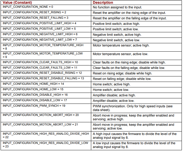
B.12.2 Input Pin Configuration Settings
The following values describe input pin configurations.
They can be read with ReadInputConfig and changed with WriteInputConfig.
Input Pin Configuration Settings (CML_INPUT_PIN_CONFIG)
| Value (Constant) | Description |
|---|---|
| INPUT_CONFIGURATION_NONE = 0 | No function assigned to the input. |
| INPUT_CONFIGURATION_RESET_RISING = 2 | Reset the amplifier on the rising edge of the input. |
| INPUT_CONFIGURATION_RESET_FALLING = 3 | Reset the amplifier on the falling edge of the input. |
| INPUT_CONFIGURATION_POSITIVE_LIMIT_HIGH = 4 | Positive limit switch; active high. |
| INPUT_CONFIGURATION_POSITIVE_LIMIT_LOW = 5 | Positive limit switch; active low. |
| INPUT_CONFIGURATION_NEGATIVE_LIMIT_HIGH = 6 | Negative limit switch, active high. |
| INPUT_CONFIGURATION_NEGATIVE_LIMIT_LOW = 7 | Negative limit switch, active low. |
| INPUT_CONFIGURATION_MOTOR_TEMPERATURE_HIGH = 8 | Motor temperature sensor; active high. |
| INPUT_CONFIGURATION_MOTOR_TEMPERATURE_LOW = 9 | Motor temperature sensor, active low. |
| INPUT_CONFIGURATION_CLEAR_FAULTS_HIGH = 10 | Clear faults on the rising edge; disable while high. |
| INPUT_CONFIGURATION_CLEAR_FAULTS_LOW = 11 | Clear faults on the falling edge, disable while low. |
| INPUT_CONFIGURATION_RESET_DISABLE_RISING = 12 | Reset on rising edge; disable while high. |
| INPUT_CONFIGURATION_RESET_DISABLE_FALLING = 13 | Reset on falling edge; disable while low. |
| INPUT_CONFIGURATION_HOME_HIGH = 14 | Home switch; active high. |
| INPUT_CONFIGURATION_HOME_LOW = 15 | Home switch; active low. |
| INPUT_CONFIGURATION_DISABLE_HIGH = 16 | Amplifier disable; active high. |
| INPUT_CONFIGURATION_DISABLE_LOW = 17 | Amplifier disable; active low. |
| INPUT_CONFIGURATION_PWM_SYNCH = 19 | PWM synchronization. Only for high speed inputs (see data sheet). |
| INPUT_CONFIGURATION_MOTION_ABORT_HIGH = 20 | Abort move in progress; keep the amplifier enabled and servoing; active high. |
| INPUT_CONFIGURATION_MOTION_ABORT_LOW = 21 | Abort move in progress; keep the amplifier enabled and servoing; active low. |
| INPUT_CONFIGURATION_HIGH_RES_ANALOG_DIVIDE_HIGH = 22 | A high input causes the firmware to divide the level of the analog input signal by 8. |
| INPUT_CONFIGURATION_HIGH_RES_ANALOG_DIVIDE_LOW = 23 | A low input causes the firmware to divide the level of the analog input signal by 8. |
Original image of the table (from the PDF manual)
B.12.3 Output Pin Methods
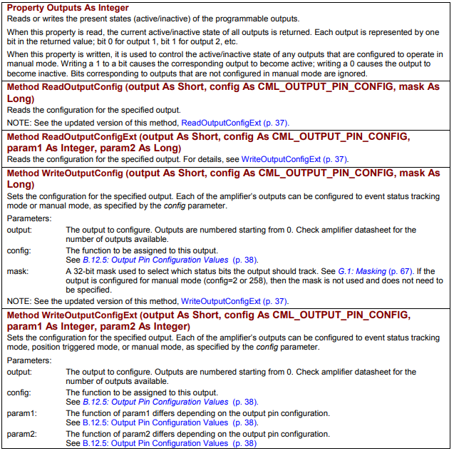
Each of the amplifier’s digital outputs can be configured to go active/inactive under different conditions. The methods and properties below, members of CMLCOMLib.AmpObj, relate to the states and configuration of the outputs.
| Member | Description |
|---|---|
Property Outputs As Integer | Reads or writes the present states (active/inactive) of the programmable outputs. When this property is read, the current active/inactive state of all outputs is returned. Each output is represented by one bit in the returned value; bit 0 for output 1, bit 1 for output 2, etc. When this property is written, it is used to control the active/inactive state of any outputs that are configured to operate in manual mode. Writing a 1 to a bit causes the corresponding output to become active; writing a 0 causes the output to become inactive. Bits corresponding to outputs that are not configured in manual mode are ignored. |
Method ReadOutputConfig (output As Short, config As CML_OUTPUT_PIN_CONFIG, mask As Long) | Reads the configuration for the specified output. NOTE: See the updated version of this method, ReadOutputConfigExt. |
Method ReadOutputConfigExt (output As Short, config As CML_OUTPUT_PIN_CONFIG, param1 As Integer, param2 As Long) | Reads the configuration for the specified output. For details, see WriteOutputConfigExt. |
Method WriteOutputConfig (output As Short, config As CML_OUTPUT_PIN_CONFIG, mask As Long) | Sets the configuration for the specified output. Each of the amplifier’s outputs can be configured to event status tracking mode or manual mode, as specified by the config parameter. Parameters: output – the output to configure; outputs are numbered starting from 0 (check amplifier datasheet for the number of outputs available); config – the function to be assigned to this output, see B.12.5: Output Pin Configuration Values; mask – a 32-bit mask used to select which status bits the output should track, see G.1: Masking; if the output is configured for manual mode (config=2 or 258), then the mask is not used and does not need to be specified. NOTE: See the updated version of this method, WriteOutputConfigExt. |
Method WriteOutputConfigExt (output As Short, config As CML_OUTPUT_PIN_CONFIG, param1 As Integer, param2 As Integer) | Sets the configuration for the specified output. Each of the amplifier’s outputs can be configured to event status tracking mode, position triggered mode, or manual mode, as specified by the config parameter. Parameters: output – the output to configure; outputs are numbered starting from 0 (check amplifier datasheet for the number of outputs available); config – the function to be assigned to this output, see B.12.5: Output Pin Configuration Values; param1 – the function of param1 differs depending on the output pin configuration, see B.12.5; param2 – the function of param2 differs depending on the output pin configuration, see B.12.5. |
Original image of the table (from the PDF manual)
B.12.5 Output Pin Configuration Values
Each value described below specifies an output pin function, and whether the output will be active high or active low. These values are set and read using the methods described in B.12.3: Output Pin Methods.
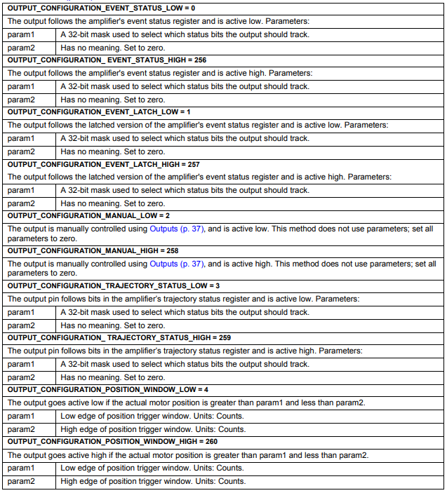
Output Pin Configuration Values (CML_OUTPUT_PIN_CONFIG) – part 1
| Value (Constant) | Description | param1 | param2 |
|---|---|---|---|
| OUTPUT_CONFIGURATION_EVENT_STATUS_LOW = 0 | The output follows the amplifier's event status register and is active low. | A 32-bit mask used to select which status bits the output should track. | Has no meaning. Set to zero. |
| OUTPUT_CONFIGURATION_EVENT_STATUS_HIGH = 256 | The output follows the amplifier's event status register and is active high. | A 32-bit mask used to select which status bits the output should track. | Has no meaning. Set to zero. |
| OUTPUT_CONFIGURATION_EVENT_LATCH_LOW = 1 | The output follows the latched version of the amplifier's event status register and is active low. | A 32-bit mask used to select which status bits the output should track. | Has no meaning. Set to zero. |
| OUTPUT_CONFIGURATION_EVENT_LATCH_HIGH = 257 | The output follows the latched version of the amplifier's event status register and is active high. | A 32-bit mask used to select which status bits the output should track. | Has no meaning. Set to zero. |
| OUTPUT_CONFIGURATION_MANUAL_LOW = 2 | The output is manually controlled using Outputs, and is active low. This method does not use parameters; set all parameters to zero. | – (no parameters; set all parameters to zero) | – (no parameters; set all parameters to zero) |
| OUTPUT_CONFIGURATION_MANUAL_HIGH = 258 | The output is manually controlled using Outputs, and is active high. This method does not use parameters; set all parameters to zero. | – (no parameters; set all parameters to zero) | – (no parameters; set all parameters to zero) |
| OUTPUT_CONFIGURATION_TRAJECTORY_STATUS_LOW = 3 | The output pin follows bits in the amplifier’s trajectory status register and is active low. | A 32-bit mask used to select which status bits the output should track. | Has no meaning. Set to zero. |
| OUTPUT_CONFIGURATION_TRAJECTORY_STATUS_HIGH = 259 | The output pin follows bits in the amplifier’s trajectory status register and is active high. | A 32-bit mask used to select which status bits the output should track. | Has no meaning. Set to zero. |
| OUTPUT_CONFIGURATION_POSITION_WINDOW_LOW = 4 | The output goes active low if the actual motor position is greater than param1 and less than param2. | Low edge of position trigger window. Units: Counts. | High edge of position trigger window. Units: Counts. |
| OUTPUT_CONFIGURATION_POSITION_WINDOW_HIGH = 260 | The output goes active high if the actual motor position is greater than param1 and less than param2. | Low edge of position trigger window. Units: Counts. | High edge of position trigger window. Units: Counts. |
Original image of the table (from the PDF manual)
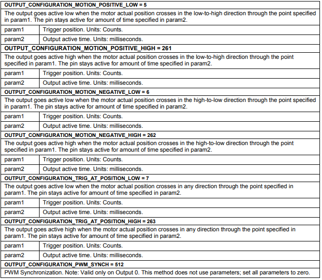
Output Pin Configuration Values (CML_OUTPUT_PIN_CONFIG) – part 2
| Value (Constant) | Description | param1 | param2 |
|---|---|---|---|
| OUTPUT_CONFIGURATION_MOTION_POSITIVE_LOW = 5 | The output goes active low when the motor actual position crosses in the low-to-high direction through the point specified in param1. The pin stays active for amount of time specified in param2. | Trigger position. Units: Counts. | Output active time. Units: milliseconds. |
| OUTPUT_CONFIGURATION_MOTION_POSITIVE_HIGH = 261 | The output goes active high when the motor actual position crosses in the low-to-high direction through the point specified in param1. The pin stays active for amount of time specified in param2. | Trigger position. Units: Counts. | Output active time. Units: milliseconds. |
| OUTPUT_CONFIGURATION_MOTION_NEGATIVE_LOW = 6 | The output goes active low when the motor actual position crosses in the high-to-low direction through the point specified in param1. The pin stays active for amount of time specified in param2. | Trigger position. Units: Counts. | Output active time. Units: milliseconds. |
| OUTPUT_CONFIGURATION_MOTION_NEGATIVE_HIGH = 262 | The output goes active high when the motor actual position crosses in the high-to-low direction through the point specified in param1. The pin stays active for amount of time specified in param2. | Trigger position. Units: Counts. | Output active time. Units: milliseconds. |
| OUTPUT_CONFIGURATION_TRIG_AT_POSITION_LOW = 7 | The output goes active low when the motor actual position crosses in any direction through the point specified in param1. The pin stays active for amount of time specified in param2. | Trigger position. Units: Counts. | Output active time. Units: milliseconds. |
| OUTPUT_CONFIGURATION_TRIG_AT_POSITION_HIGH = 263 | The output goes active high when the motor actual position crosses in any direction through the point specified in param1. The pin stays active for amount of time specified in param2. | Trigger position. Units: Counts. | Output active time. Units: milliseconds. |
| OUTPUT_CONFIGURATION_PWM_SYNCH = 512 | PWM Synchronization. Note: Valid only on Output 0. This method does not use parameters; set all parameters to zero. | – (no parameters; set all parameters to zero) | – (no parameters; set all parameters to zero) |
Original image of the table (from the PDF manual)
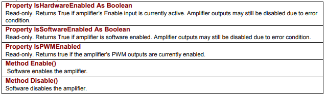
B.13 Amplifier Enable/Disable
The following methods and properties of the AmpObj object are used to enable and disable the amplifier, and report on its state.
| Member | Description |
|---|---|
Property IsHardwareEnabled As Boolean | Read-only. Returns True if amplifier's Enable input is currently active. Amplifier outputs may still be disabled due to error condition. |
Property IsSoftwareEnabled As Boolean | Read-only. Returns True if amplifier is software enabled. Amplifier outputs may still be disabled due to error condition. |
Property IsPWMEnabled | Read-only. Returns true if the amplifier's PWM outputs are currently enabled. |
Method Enable() | Software enables the amplifier. |
Method Disable() | Software disables the amplifier. |
Original image of the table (from the PDF manual)
Słowa kluczowe
ReadEventStatus, CML_EVENT_STATUS, CML_AMP_EVENT, CML_AMP_FAULT, FaultMask, ReadFaults, ClearFaults, Inputs, WriteInputConfig, CML_INPUT_PIN_CONFIG, Outputs, WriteOutputConfigExt, CML_OUTPUT_PIN_CONFIG, Enable, Disable