
Appendix B: Amplifier and Related Objects (B.14–B.19) – homing, quick stop, moves, events, trace, other
Streszczenie: Obiekt AmpObj, część 3: bazowanie (GoHome, HomeSettings, metody CML_HOME_METHOD), szybkie zatrzymanie i halt, ruchy punkt-punkt (MoveRel, MoveAbs, ProfileSettings, typy profili), zdarzenia napędu (CreateEvent), funkcje trace (kanały, wyzwalanie, zmienne CML_TRACE_VAR) oraz pozostałe metody i właściwości (jednostki, temperatura, tryb pracy CML_AMP_MODE, transfery SDO).
EN: Amplifier object part 3: homing, quick stop/halt, point-to-point moves, events, trace, other methods and properties.
Dotyczy: Copley Motion Objects (CMO, biblioteka COM CMLCOMLib) – sterowanie serwonapędami Copley CANopen z PC (Windows; VB 6.0, VB .NET, LabVIEW)
Źródło: dokumentacja producenta (Copley Motion Objects Programmer’s Guide); tabele przepisane z obrazów na tekst – opracowanie Multiprojekt
B.14 Homing
B.14.1 Homing-Related Amplifier Object Methods and Properties
The following homing methods and properties are members of CMLCOMLib.AmpObj
| Member | Description |
|---|---|
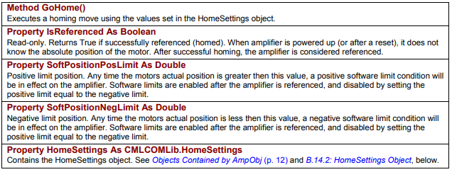
Method GoHome() | Executes a homing move using the values set in the HomeSettings object. |
Property IsReferenced As Boolean | Read-only. Returns True if successfully referenced (homed). When amplifier is powered up (or after a reset), it does not know the absolute position of the motor. After successful homing, the amplifier is considered referenced. |
Property SoftPositionPosLimit As Double | Positive limit position. Any time the motors actual position is greater then this value, a positive software limit condition will be in effect on the amplifier. Software limits are enabled after the amplifier is referenced, and disabled by setting the positive limit equal to the negative limit. |
Property SoftPositionNegLimit As Double | Negative limit position. Any time the motors actual position is less then this value, a negative software limit condition will be in effect on the amplifier. Software limits are enabled after the amplifier is referenced, and disabled by setting the positive limit equal to the negative limit. |
Property HomeSettings As CMLCOMLib.HomeSettings | Contains the HomeSettings object. See Objects Contained by AmpObj and B.14.2: HomeSettings Object, below. |
Original image of the table (from the PDF manual)
B.14.2 HomeSettings Object Properties
The following homing properties are members of CMLCOMLib.HomeSettings. An instance of this object is obtained from the AmpObj.
| Member | Description |
|---|---|
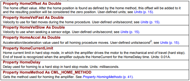
Property HomeOffset As Double | The home offset value. After the home position is found as defined by the home method, this offset will be added to it and the resulting position will be considered the zero position. User-defined units; see Units. |
Property HomeVelFast As Double | Velocity to use for fast moves during the home procedure. User-defined units/second; see Units. |
Property HomeVelSlow As Double | Velocity to use when seeking a sensor edge. User-defined units/second; see Units. |
Property HomeAccel As Double | Acceleration/deceleration value used for all homing procedure moves. User-defined units/second²; see Units. |
Property HomeCurrentLimit | Home current limit in hard stop mode, in which the amplifier drives the motor to the mechanical end of travel (hard stop). End of travel is recognized when the amplifier outputs the HomeCurrent for the HomeDelay time. Units: 0.01A. |
Property HomeDelay | Delay used for homing to a hard stop in hard stop mode. Units: milliseconds. |
Property HomeMethod As CML_HOME_METHOD | Gets the method used for homing the amplifier. See Property HomingMethods. |
Original image of the table (from the PDF manual)
Property HomingMethods – values (CML_HOME_METHOD), part 1
| Value (Const) | Description |
|---|---|
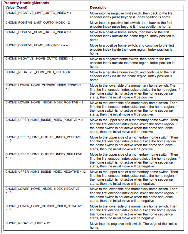
| CHOME_NEGATIVE_LIMIT_OUTTO_INDEX = 1 | Move into the negative limit switch, then back to the first encoder index pulse beyond it. Index position is home. |
| CHOME_POSITIVE_LIMIT_OUTTO_INDEX = 2 | Move into the positive limit switch, then back to the first encoder index pulse beyond it. Index position is home. |
| CHOME_POSITIVE_HOME_OUTTO_INDEX = 3 | Move to a positive home switch, then back to the first encoder index outside the home region. Index position is home. |
| CHOME_POSITIVE_HOME_INTO_INDEX = 4 | Move to a positive home switch, and continue to the first encoder index inside the home region. Index position is home. |
| CHOME_NEGATIVE_HOME_OUTTO_INDEX = 5 | Move to a negative home switch, then back to the first encoder index outside the home region. Index position is home. |
| CHOME_NEGATIVE_HOME_INTO_INDEX = 6 | Move to a negative home switch, and continue to the first encoder index inside the home region. Index position is home. |
| CHOME_LOWER_HOME_OUTSIDE_INDEX_POSITIVE = 7 | Move to the lower side of a momentary home switch. Then find the first encoder index pulse outside the home region. If the home switch is not active when the home sequence starts, then the initial move will be positive. |
| CHOME_LOWER_HOME_INSIDE_INDEX_POSITIVE = 8 | Move to the lower side of a momentary home switch. Then find the first encoder index pulse inside the home region. If the home switch is not active when the home sequence starts, then the initial move will be positive. |
| CHOME_UPPER_HOME_INSIDE_INDEX_POSITIVE = 9 | Move to the upper side of a momentary home switch. Then find the first encoder index pulse inside the home region. If the home switch is not active when the home sequence starts, then the initial move will be positive. |
| CHOME_UPPER_HOME_OUTSIDE_INDEX_POSITIVE = 10 | Move to the upper side of a momentary home switch. Then find the first encoder index pulse outside the home region. If the home switch is not active when the home sequence starts, then the initial move will be positive. |
| CHOME_UPPER_HOME_OUTSIDE_INDEX_NEGATIVE = 11 | Move to the upper side of a momentary home switch. Then find the first encoder index pulse outside the home region. If the home switch is not active when the home sequence starts, then the initial move will be negative. |
| CHOME_UPPER_HOME_INSIDE_INDEX_NEGATIVE = 12 | Move to the upper side of a momentary home switch. Then find the first encoder index pulse inside the home region. If the home switch is not active when the home sequence starts, then the initial move will be negative. |
| CHOME_LOWER_HOME_INSIDE_INDEX_NEGATIVE = 13 | Move to the lower side of a momentary home switch. Then find the first encoder index pulse inside the home region. If the home switch is not active when the home sequence starts, then the initial move will be negative. |
| CHOME_LOWER_HOME_OUTSIDE_INDEX_NEGATIVE = 14 | Move to the lower side of a momentary home switch. Then find the first encoder index pulse outside the home region. If the home switch is not active when the home sequence starts, then the initial move will be negative. |
| CHOME_NEGATIVE_LIMIT = 17 | Move into the negative limit switch. The edge of the limit is home. |
Original image of the table (from the PDF manual)
Property HomingMethods – values (CML_HOME_METHOD), part 2
| Value (Const) | Description |
|---|---|
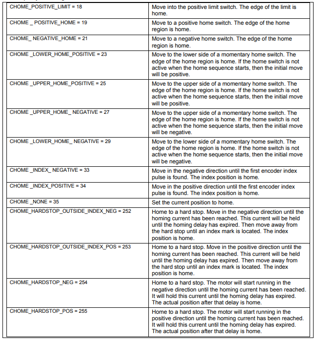
| CHOME_POSITIVE_LIMIT = 18 | Move into the positive limit switch. The edge of the limit is home. |
| CHOME_POSITIVE_HOME = 19 | Move to a positive home switch. The edge of the home region is home. |
| CHOME_NEGATIVE_HOME = 21 | Move to a negative home switch. The edge of the home region is home. |
| CHOME_LOWER_HOME_POSITIVE = 23 | Move to the lower side of a momentary home switch. The edge of the home region is home. If the home switch is not active when the home sequence starts, then the initial move will be positive. |
| CHOME_UPPER_HOME_POSITIVE = 25 | Move to the upper side of a momentary home switch. The edge of the home region is home. If the home switch is not active when the home sequence starts, then the initial move will be positive. |
| CHOME_UPPER_HOME_NEGATIVE = 27 | Move to the upper side of a momentary home switch. The edge of the home region is home. If the home switch is not active when the home sequence starts, then the initial move will be negative. |
| CHOME_LOWER_HOME_NEGATIVE = 29 | Move to the lower side of a momentary home switch. The edge of the home region is home. If the home switch is not active when the home sequence starts, then the initial move will be negative. |
| CHOME_INDEX_NEGATIVE = 33 | Move in the negative direction until the first encoder index pulse is found. The index position is home. |
| CHOME_INDEX_POSITIVE = 34 | Move in the positive direction until the first encoder index pulse is found. The index position is home. |
| CHOME_NONE = 35 | Set the current position to home. |
| CHOME_HARDSTOP_OUTSIDE_INDEX_NEG = 252 | Home to a hard stop. Move in the negative direction until the homing current has been reached. This current will be held until the homing delay has expired. Then move away from the hard stop until an index mark is located. The index position is home. |
| CHOME_HARDSTOP_OUTSIDE_INDEX_POS = 253 | Home to a hard stop. Move in the positive direction until the homing current has been reached. This current will be held until the homing delay has expired. Then move away from the hard stop until an index mark is located. The index position is home. |
| CHOME_HARDSTOP_NEG = 254 | Home to a hard stop. The motor will start running in the negative direction until the homing current has been reached. It will hold this current until the homing delay has expired. The actual position after that delay is home. |
| CHOME_HARDSTOP_POS = 255 | Home to a hard stop. The motor will start running in the positive direction until the homing current has been reached. It will hold this current until the homing delay has expired. The actual position after that delay is home. |
Original image of the table (from the PDF manual)
B.15 Quick Stop
Quick stops are controlled using these methods and properties of the CMLCOMLib.AmpObj object.
B.15.1 Quick Stop
The following properties and methods, members of CMLCOMLib.AmpObj, are used to configure
the amplifier’s quick stop action.
| Member | Description |
|---|---|
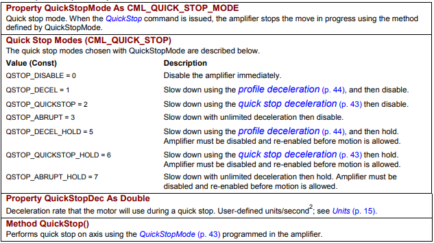
Property QuickStopMode As CML_QUICK_STOP_MODE | Quick stop mode. When the QuickStop command is issued, the amplifier stops the move in progress using the method defined by QuickStopMode. |
Quick Stop Modes (CML_QUICK_STOP)
| Value (Const) | Description |
|---|---|
| QSTOP_DISABLE = 0 | Disable the amplifier immediately. |
| QSTOP_DECEL = 1 | Slow down using the profile deceleration, and then disable. |
| QSTOP_QUICKSTOP = 2 | Slow down using the quick stop deceleration then disable. |
| QSTOP_ABRUPT = 3 | Slow down with unlimited deceleration then disable. |
| QSTOP_DECEL_HOLD = 5 | Slow down using the profile deceleration, and then hold. Amplifier must be disabled and re-enabled before motion is allowed. |
| QSTOP_QUICKSTOP_HOLD = 6 | Slow down using the quick stop deceleration then hold. Amplifier must be disabled and re-enabled before motion is allowed. |
| QSTOP_ABRUPT_HOLD = 7 | Slow down with unlimited deceleration then hold. Amplifier must be disabled and re-enabled before motion is allowed. |
| Member | Description |
|---|---|
Property QuickStopDec As Double | Deceleration rate that the motor will use during a quick stop. User-defined units/second²; see Units. |
Method QuickStop() | Performs quick stop on axis using the QuickStopMode programmed in the amplifier. |
Original image of the table (from the PDF manual)
B.15.2 Halt
The following properties and methods, members of CMLCOMLib.AmpObj, are used to configure the amplifier’s halt action.
| Member | Description |
|---|---|
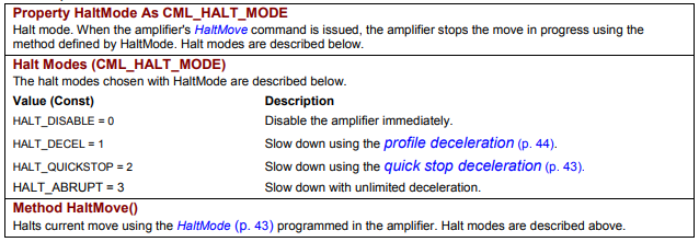
Property HaltMode As CML_HALT_MODE | Halt mode. When the amplifier’s HaltMove command is issued, the amplifier stops the move in progress using the method defined by HaltMode. Halt modes are described below. |
Halt Modes (CML_HALT_MODE)
| Value (Const) | Description |
|---|---|
| HALT_DISABLE = 0 | Disable the amplifier immediately. |
| HALT_DECEL = 1 | Slow down using the profile deceleration. |
| HALT_QUICKSTOP = 2 | Slow down using the quick stop deceleration. |
| HALT_ABRUPT = 3 | Slow down with unlimited deceleration. |
| Member | Description |
|---|---|
Method HaltMove() | Halts current move using the HaltMode programmed in the amplifier. Halt modes are described above. |
Original image of the table (from the PDF manual)
B.16 Point-to-Point Moves
B.16.1 Point-to-Point Move-Related Amplifier Methods and Properties
The following methods and properties, members of CMLCOMLib.AmpObj, can be used to control
point-to-point moves
| Member | Description |
|---|---|
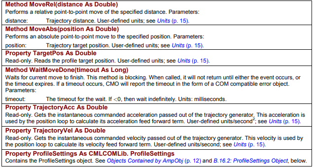
Method MoveRel(distance As Double) | Performs a relative point-to-point move of the specified distance. Parameters: distance – trajectory distance. User-defined units; see Units. |
Method MoveAbs(position As Double) | Performs an absolute point-to-point move to the specified position. Parameters: position – trajectory target position. User-defined units; see Units. |
Property TargetPos As Double | Read-only. Reads the profile target position. User-defined units; see Units. |
Method WaitMoveDone(timeout As Long) | Waits for current move to finish. This method is blocking. When called, it will not return until either the event occurs, or the timeout expires. If a timeout occurs, CMO will report the timeout in the form of a COM compatible error object. Parameters: timeout – the timeout for the wait. If <0, then wait indefinitely. Units: milliseconds. |
Property TrajectoryAcc As Double | Read-only. Gets the instantaneous commanded acceleration passed out of the trajectory generator. This acceleration is used by the position loop to calculate its acceleration feed forward term. User-defined units/second²; see Units. |
Property TrajectoryVel As Double | Read-only. Gets the instantaneous commanded velocity passed out of the trajectory generator. This velocity is used by the position loop to calculate its velocity feed forward term. User-defined units/second; see Units. |
Property ProfileSettings As CMLCOMLib.ProfileSettings | Contains the ProfileSettings object. See Objects Contained by AmpObj and B.16.2: ProfileSettings Object, below. |
Original image of the table (from the PDF manual)
B.16.2 ProfileSettings Object
The following point-to-point move properties are members of CMLCOMLib.ProfileSettings. An instance of this object is obtained from the AmpObj.
| Member | Description |
|---|---|
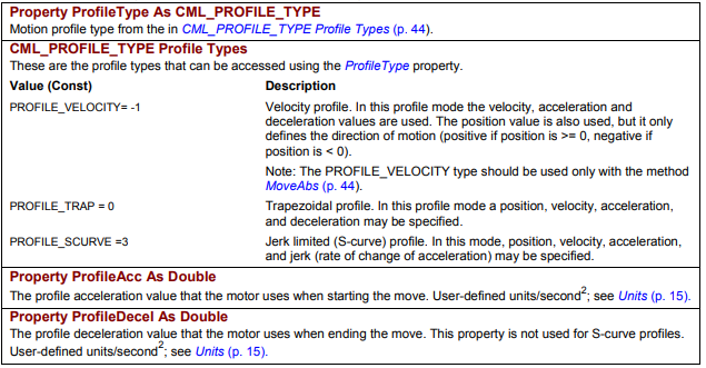
Property ProfileType As CML_PROFILE_TYPE | Motion profile type from the CML_PROFILE_TYPE Profile Types (below). |
CML_PROFILE_TYPE Profile Types (accessed using the ProfileType property)
| Value (Const) | Description |
|---|---|
| PROFILE_VELOCITY = -1 | Velocity profile. In this profile mode the velocity, acceleration and deceleration values are used. The position value is also used, but it only defines the direction of motion (positive if position is >= 0, negative if position is < 0). Note: The PROFILE_VELOCITY type should be used only with the method MoveAbs. |
| PROFILE_TRAP = 0 | Trapezoidal profile. In this profile mode a position, velocity, acceleration, and deceleration may be specified. |
| PROFILE_SCURVE = 3 | Jerk limited (S-curve) profile. In this mode, position, velocity, acceleration, and jerk (rate of change of acceleration) may be specified. |
| Member | Description |
|---|---|
Property ProfileAcc As Double | The profile acceleration value that the motor uses when starting the move. User-defined units/second²; see Units. |
Property ProfileDecel As Double | The profile deceleration value that the motor uses when ending the move. This property is not used for S-curve profiles. User-defined units/second²; see Units. |
Original image of the table (from the PDF manual)
| Member | Description |
|---|---|
Property ProfileJerk As Double | The jerk limit used with S-curve profiles. Jerk is rate of change of acceleration. Only used with S-curve profiles. User-defined units/second³; see Units. |
Property ProfileVel As Double | The profile velocity value that the motor attempts to reach during the move. User-defined units/second; see Units. |
Property ProfileAbort | Deceleration value to use when aborting a running trajectory. User-defined units/second²; see Units. |
Original image of the table (from the PDF manual)

B.17 Amplifier Events
The following methods, members of CMLCOMLib.AmpObj, are used to monitor amplifier events and amplifier inputs.
| Member | Description |
|---|---|
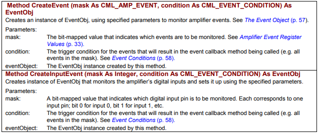
Method CreateEvent (mask As CML_AMP_EVENT, condition As CML_EVENT_CONDITION) As EventObj | Creates an instance of EventObj, using specified parameters to monitor amplifier events. See The Event Object (Appendix D). Parameters: mask – the bit-mapped value that indicates which events are to be monitored, see Amplifier Event Register Values; condition – the trigger condition for the events that will result in the event callback method being called (e.g. all events in the mask), see Event Conditions; eventObject – the EventObj instance created by this method. |
Method CreateInputEvent (mask As Integer, condition As CML_EVENT_CONDITION) As EventObj | Creates instance of EventObj that monitors the amplifier’s digital inputs and sets it up using the specified parameters. Parameters: mask – a bit-mapped value that indicates which digital input pin is to be monitored; each corresponds to one input pin; bit 0 for input 0, bit 1 for input 1, etc.; condition – the trigger condition for the events that will result in the event callback method being called (e.g. all events in the mask), see Event Conditions; eventObject – the EventObj instance created by this method. |
Original image of the table (from the PDF manual)
B.18 Amplifier Trace Methods and Properties
The following methods are used to configure and monitor the amplifier trace function.
B.18.1 Amplifier Trace Methods
The following amplifier trace methods are members of CMLCOMLib.AmpObj
| Member | Description |
|---|---|
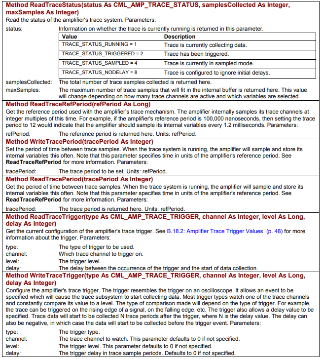
Method ReadTraceStatus(status As CML_AMP_TRACE_STATUS, samplesCollected As Integer, maxSamples As Integer) | Read the status of the amplifier's trace system. Parameters: status – information on whether the trace is currently running is returned in this parameter (values below); samplesCollected – the total number of trace samples collected is returned here; maxSamples – the maximum number of trace samples that will fit in the internal buffer is returned here. This value will change depending on how many trace channels are active and which variables are selected. |
CML_AMP_TRACE_STATUS values
| Value | Description |
|---|---|
| TRACE_STATUS_RUNNING = 1 | Trace is currently collecting data. |
| TRACE_STATUS_TRIGGERED = 2 | Trace has been triggered. |
| TRACE_STATUS_SAMPLED = 4 | Trace is currently in sampled mode. |
| TRACE_STATUS_NODELAY = 8 | Trace is configured to ignore initial delays. |
| Member | Description |
|---|---|
Method ReadTraceRefPeriod(refPeriod As Long) | Get the reference period used with the amplifier's trace mechanism. The amplifier internally samples its trace channels at integer multiples of this time. For example, if the amplifier's reference period is 100,000 nanoseconds, then setting the trace period to 12 would indicate that the amplifier should sample its internal variables every 1.2 milliseconds. Parameters: refPeriod – the reference period is returned here. Units: refPeriod. |
Method WriteTracePeriod(tracePeriod As Integer) | Set the period of time between trace samples. When the trace system is running, the amplifier will sample and store its internal variables this often. Note that this parameter specifies time in units of the amplifier's reference period. See ReadTraceRefPeriod for more information. Parameters: tracePeriod – the trace period to be set. Units: refPeriod. |
Method ReadTracePeriod(tracePeriod As Integer) | Get the period of time between trace samples. When the trace system is running, the amplifier will sample and store its internal variables this often. Note that this parameter specifies time in units of the amplifier's reference period. See ReadTraceRefPeriod for more information. Parameters: tracePeriod – the trace period is returned here. Units: refPeriod. |
Method ReadTraceTrigger(type As CML_AMP_TRACE_TRIGGER, channel As Integer, level As Long, delay As Integer) | Get the current configuration of the amplifier's trace trigger. See B.18.2: Amplifier Trace Trigger Values for more information about the trigger. Parameters: type – the type of trigger to be used; channel – which trace channel to trigger on; level – the trigger level; delay – the delay between the occurrence of the trigger and the start of data collection. |
Method WriteTraceTrigger(type As CML_AMP_TRACE_TRIGGER, channel As Integer, level As Long, delay As Integer) | Configure the amplifier's trace trigger. The trigger resembles the trigger on an oscilloscope. It allows an event to be specified which will cause the trace subsystem to start collecting data. Most trigger types watch one of the trace channels and constantly compare its value to a level. The type of comparison made will depend on the type of trigger. For example, the trace can be triggered on the rising edge of a signal, on the falling edge, etc. The trigger also allows a delay value to be specified. Trace data will start to be collected N trace periods after the trigger, where N is the delay value. The delay can also be negative, in which case the data will start to be collected before the trigger event. Parameters: type – the trigger type; channel – the trace channel to watch (defaults to 0 if not specified); level – the trigger level (defaults to 0 if not specified); delay – the trigger delay in trace sample periods (defaults to 0 if not specified). |
Original image of the table (from the PDF manual)
| Member | Description |
|---|---|
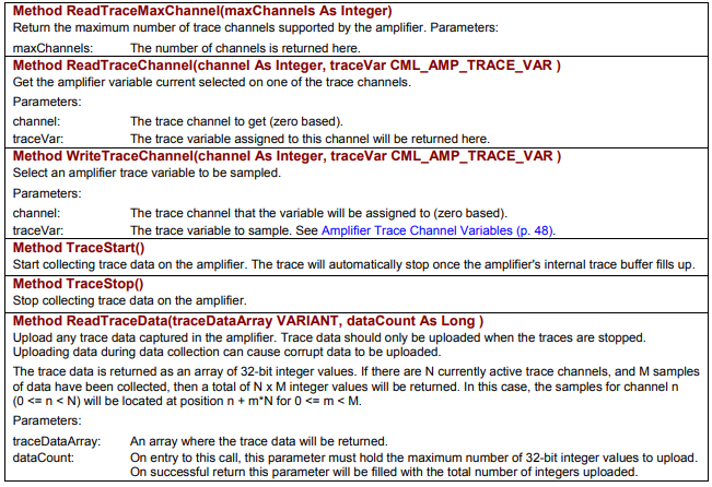
Method ReadTraceMaxChannel(maxChannels As Integer) | Return the maximum number of trace channels supported by the amplifier. Parameters: maxChannels – the number of channels is returned here. |
Method ReadTraceChannel(channel As Integer, traceVar CML_AMP_TRACE_VAR) | Get the amplifier variable current selected on one of the trace channels. Parameters: channel – the trace channel to get (zero based); traceVar – the trace variable assigned to this channel will be returned here. |
Method WriteTraceChannel(channel As Integer, traceVar CML_AMP_TRACE_VAR) | Select an amplifier trace variable to be sampled. Parameters: channel – the trace channel that the variable will be assigned to (zero based); traceVar – the trace variable to sample. See Amplifier Trace Channel Variables. |
Method TraceStart() | Start collecting trace data on the amplifier. The trace will automatically stop once the amplifier's internal trace buffer fills up. |
Method TraceStop() | Stop collecting trace data on the amplifier. |
Method ReadTraceData(traceDataArray VARIANT, dataCount As Long) | Upload any trace data captured in the amplifier. Trace data should only be uploaded when the traces are stopped. Uploading data during data collection can cause corrupt data to be uploaded. The trace data is returned as an array of 32-bit integer values. If there are N currently active trace channels, and M samples of data have been collected, then a total of N x M integer values will be returned. In this case, the samples for channel n (0 <= n < N) will be located at position n + m*N for 0 <= m < M. Parameters: traceDataArray – an array where the trace data will be returned; dataCount – on entry to this call, this parameter must hold the maximum number of 32-bit integer values to upload. On successful return this parameter will be filled with the total number of integers uploaded. |
Original image of the table (from the PDF manual)
B.18.2 Amplifier Trace Trigger Values
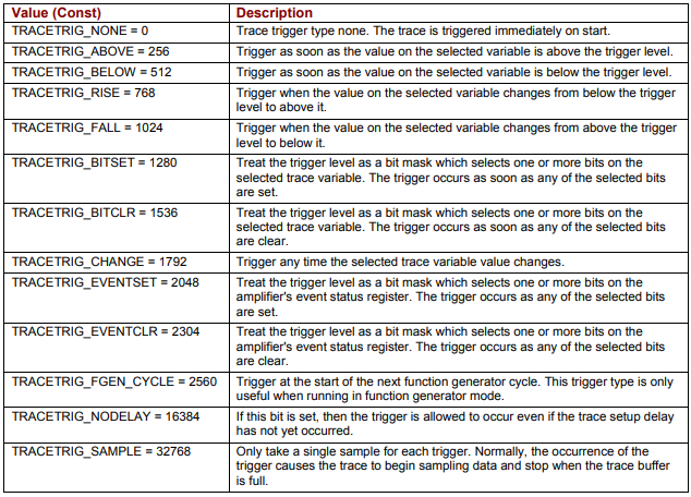
The method WriteTraceTrigger (p. 46) can be used to configure the trace trigger by selecting one of the values below. The method ReadTraceTrigger (p. 46) can be used to read the current trigger value.
Amplifier Trace Trigger Values (CML_AMP_TRACE_TRIGGER)
| Value (Const) | Description |
|---|---|
| TRACETRIG_NONE = 0 | Trace trigger type none. The trace is triggered immediately on start. |
| TRACETRIG_ABOVE = 256 | Trigger as soon as the value on the selected variable is above the trigger level. |
| TRACETRIG_BELOW = 512 | Trigger as soon as the value on the selected variable is below the trigger level. |
| TRACETRIG_RISE = 768 | Trigger when the value on the selected variable changes from below the trigger level to above it. |
| TRACETRIG_FALL = 1024 | Trigger when the value on the selected variable changes from above the trigger level to below it. |
| TRACETRIG_BITSET = 1280 | Treat the trigger level as a bit mask which selects one or more bits on the selected trace variable. The trigger occurs as soon as any of the selected bits are set. |
| TRACETRIG_BITCLR = 1536 | Treat the trigger level as a bit mask which selects one or more bits on the selected trace variable. The trigger occurs as soon as any of the selected bits are clear. |
| TRACETRIG_CHANGE = 1792 | Trigger any time the selected trace variable value changes. |
| TRACETRIG_EVENTSET = 2048 | Treat the trigger level as a bit mask which selects one or more bits on the amplifier's event status register. The trigger occurs as any of the selected bits are set. |
| TRACETRIG_EVENTCLR = 2304 | Treat the trigger level as a bit mask which selects one or more bits on the amplifier's event status register. The trigger occurs as any of the selected bits are clear. |
| TRACETRIG_FGEN_CYCLE = 2560 | Trigger at the start of the next function generator cycle. This trigger type is only useful when running in function generator mode. |
| TRACETRIG_NODELAY = 16384 | If this bit is set, then the trigger is allowed to occur even if the trace setup delay has not yet occurred. |
| TRACETRIG_SAMPLE = 32768 | Only take a single sample for each trigger. Normally, the occurrence of the trigger causes the trace to begin sampling data and stop when the trace buffer is full. |
Original image of the table (from the PDF manual)
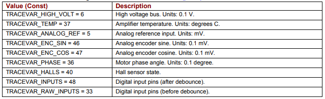
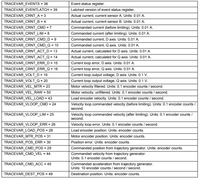
B.18.3 Amplifier Trace Channel Variables
Following is the list of amplifier variables that can be monitored using the trace feature. A variable can be assigned to a channel using method WriteTraceChannel. A channel’s assigned variable can be read using method ReadTraceChannel.
Trace variables (CML_TRACE_VAR) – part 1
| Value (Const) | Description |
|---|---|
| TRACEVAR_HIGH_VOLT = 6 | High voltage bus. Units: 0.1 V. |
| TRACEVAR_TEMP = 37 | Amplifier temperature. Units: degrees C. |
| TRACEVAR_ANALOG_REF = 5 | Analog reference input. Units: mV. |
| TRACEVAR_ENC_SIN = 46 | Analog encoder sine. Units: 0.1 mV. |
| TRACEVAR_ENC_COS = 47 | Analog encoder cosine. Units: 0.1 mV. |
| TRACEVAR_PHASE = 36 | Motor phase angle. Units: 0.1 degree. |
| TRACEVAR_HALLS = 40 | Hall sensor state. |
| TRACEVAR_INPUTS = 48 | Digital input pins (after debounce). |
| TRACEVAR_RAW_INPUTS = 33 | Digital input pins (before debounce). |
Original image of the table (from the PDF manual)
Trace variables (CML_TRACE_VAR) – part 2
| Value (Const) | Description |
|---|---|
| TRACEVAR_EVENTS = 38 | Event status register. |
| TRACEVAR_EVENTLATCH = 39 | Latched version of event status register. |
| TRACEVAR_CRNT_A = 3 | Actual current, current sensor A. Units: 0.01 A. |
| TRACEVAR_CRNT_B = 4 | Actual current, current sensor B. Units: 0.01 A. |
| TRACEVAR_CRNT_CMD = 7 | Commanded current (before limiting). Units: 0.01 A. |
| TRACEVAR_CRNT_LIM = 8 | Commanded current (after limiting). Units: 0.01 A. |
| TRACEVAR_CRNT_CMD_D = 9 | Commanded current, D axis. Units: 0.01 A. |
| TRACEVAR_CRNT_CMD_Q = 10 | Commanded current, Q axis. Units: 0.01 A. |
| TRACEVAR_CRNT_ACT_D = 13 | Actual current, calculated for D axis. Units: 0.01 A. |
| TRACEVAR_CRNT_ACT_Q = 14 | Actual current, calculated for Q axis. Units: 0.01 A. |
| TRACEVAR_CRNT_ERR_D = 15 | Current loop error, D axis. Units: 0.01 A. |
| TRACEVAR_CRNT_ERR_Q = 16 | Current loop error, Q axis. Units: 0.01 A. |
| TRACEVAR_VOLT_D = 19 | Current loop output voltage, D axis. Units: 0.1 V. |
| TRACEVAR_VOLT_Q = 20 | Current loop output voltage, Q axis. Units: 0.1 V. |
| TRACEVAR_VEL_MTR = 23 | Motor velocity filtered. Units: 0.1 encoder counts / second. |
| TRACEVAR_VEL_RAW = 50 | Motor velocity, unfiltered. Units: 0.1 encoder counts / second. |
| TRACEVAR_VEL_LOAD = 43 | Load encoder velocity. Units: 0.1 encoder counts / second. |
| TRACEVAR_VLOOP_CMD = 24 | Velocity loop commanded velocity (before limiting). Units: 0.1 encoder counts / second. |
| TRACEVAR_VLOOP_LIM = 25 | Velocity loop commanded velocity (after limiting). Units: 0.1 encoder counts / second. |
| TRACEVAR_VLOOP_ERR = 26 | Velocity loop error. Units: 0.1 encoder counts / second. |
| TRACEVAR_LOAD_POS = 28 | Load encoder position. Units: encoder counts. |
| TRACEVAR_MTR_POS = 31 | Motor encoder position. Units: encoder counts. |
| TRACEVAR_POS_ERR = 30 | Position error. Units: encoder counts. |
| TRACEVAR_CMD_POS = 29 | Commanded position from trajectory generator. Units: encoder counts. |
| TRACEVAR_CMD_VEL = 44 | Commanded velocity from trajectory generator. Units: 0.1 encoder counts / second. |
| TRACEVAR_CMD_ACC = 45 | Commanded acceleration from trajectory generator. Units: 10 encoder counts / second / second. |
| TRACEVAR_DEST_POS = 49 | Destination position. Units: encoder counts. |
Original image of the table (from the PDF manual)
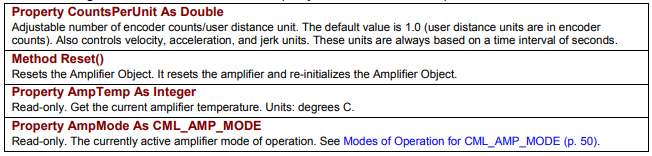
B.19 Other Methods and Properties
The following members of CMLCOMLib.AmpObj relate to various amplifier functions.
| Member | Description |
|---|---|
Property CountsPerUnit As Double | Adjustable number of encoder counts/user distance unit. The default value is 1.0 (user distance units are in encoder counts). Also controls velocity, acceleration, and jerk units. These units are always based on a time interval of seconds. |
Method Reset() | Resets the Amplifier Object. It resets the amplifier and re-initializes the Amplifier Object. |
Property AmpTemp As Integer | Read-only. Get the current amplifier temperature. Units: degrees C. |
Property AmpMode As CML_AMP_MODE | Read-only. The currently active amplifier mode of operation. See Modes of Operation for CML_AMP_MODE. |
Original image of the table (from the PDF manual)
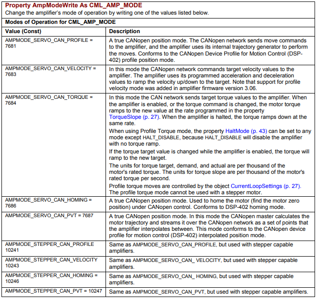
| Member | Description |
|---|---|
Property AmpModeWrite As CML_AMP_MODE | Change the amplifier's mode of operation by writing one of the values listed below. |
Modes of Operation for CML_AMP_MODE
| Value (Const) | Description |
|---|---|
| AMPMODE_SERVO_CAN_PROFILE = 7681 | A true CANopen position mode. The CANopen network sends move commands to the amplifier, and the amplifier uses its internal trajectory generator to perform the moves. Conforms to the CANopen Device Profile for Motion Control (DSP-402) profile position mode. |
| AMPMODE_SERVO_CAN_VELOCITY = 7683 | In this mode the CANopen network commands target velocity values to the amplifier. The amplifier uses its programmed acceleration and deceleration values to ramp the velocity up/down to the target. Note that support for profile velocity mode was added in amplifier firmware version 3.06. |
| AMPMODE_SERVO_CAN_TORQUE = 7684 | In this mode the CAN network sends target torque values to the amplifier. When the amplifier is enabled, or the torque command is changed, the motor torque ramps to the new value at the rate programmed in the property TorqueSlope. When the amplifier is halted, the torque ramps down at the same rate. When using Profile Torque mode, the property HaltMode can be set to any mode except HALT_DISABLE, because HALT_DISABLE will disable the amplifier with no torque ramp. If the torque target value is changed while the amplifier is enabled, the torque will ramp to the new target. The units for torque target, demand, and actual are per thousand of the motor's rated torque. The units for torque slope are per thousand of the motor's rated torque per second. Profile torque moves are controlled by the object CurrentLoopSettings. The profile torque mode cannot be used with a stepper motor. |
| AMPMODE_SERVO_CAN_HOMING = 7686 | A true CANopen position mode. Used to home the motor (find the motor zero position) under CANopen control. Conforms to DSP-402 homing mode. |
| AMPMODE_SERVO_CAN_PVT = 7687 | A true CANopen position mode. In this mode the CANopen master calculates the motor trajectory and streams it over the CANopen network as a set of points that the amplifier interpolates between. This mode conforms to the CANopen device profile for motion control (DSP-402) interpolated position mode. |
| AMPMODE_STEPPER_CAN_PROFILE = 10241 | Same as AMPMODE_SERVO_CAN_PROFILE, but used with stepper capable amplifiers. |
| AMPMODE_STEPPER_CAN_VELOCITY = 10243 | Same as AMPMODE_SERVO_CAN_VELOCITY, but used with stepper capable amplifiers. |
| AMPMODE_STEPPER_CAN_HOMING = 10246 | Same as AMPMODE_SERVO_CAN_HOMING, but used with stepper capable amplifiers. |
| AMPMODE_STEPPER_CAN_PVT = 10247 | Same as AMPMODE_SERVO_CAN_PVT, but used with stepper capable amplifiers. |
Original image of the table (from the PDF manual)
| Member | Description |
|---|---|
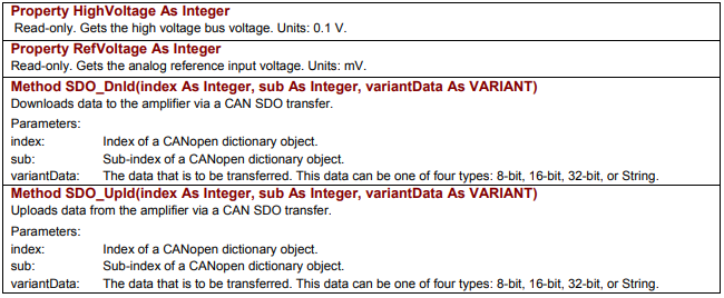
Property HighVoltage As Integer | Read-only. Gets the high voltage bus voltage. Units: 0.1 V. |
Property RefVoltage As Integer | Read-only. Gets the analog reference input voltage. Units: mV. |
Method SDO_Dnld(index As Integer, sub As Integer, variantData As VARIANT) | Downloads data to the amplifier via a CAN SDO transfer. Parameters: index – index of a CANopen dictionary object; sub – sub-index of a CANopen dictionary object; variantData – the data that is to be transferred. This data can be one of four types: 8-bit, 16-bit, 32-bit, or String. |
Method SDO_Upld(index As Integer, sub As Integer, variantData As VARIANT) | Uploads data from the amplifier via a CAN SDO transfer. Parameters: index – index of a CANopen dictionary object; sub – sub-index of a CANopen dictionary object; variantData – the data that is to be transferred. This data can be one of four types: 8-bit, 16-bit, 32-bit, or String. |
Original image of the table (from the PDF manual)
Słowa kluczowe
GoHome, HomeSettings, CML_HOME_METHOD, QuickStop, HaltMove, MoveRel, MoveAbs, ProfileSettings, PROFILE_TRAP, PROFILE_SCURVE, CreateEvent, trace, WriteTraceTrigger, TRACEVAR, CountsPerUnit, AmpModeWrite, CML_AMP_MODE, SDO_Dnld, SDO_Upld