
4. Functions (4.13–4.24) – motion and operating mode functions
Streszczenie: Funkcje Indexer 2, część 2: funkcje ruchu i trybów pracy – Velocity Move (tryb pozycyjny i prędkościowy), Move (względny/bezwzględny, profil trapezowy/S-curve), Home, Current Move, Analog Velocity Mode, Analog Position Mode, Disable Amplifier, Camming Internal Master, Camming, Digital Position Mode i Velocity Loop Single Pole Out – z parametrami i jednostkami rejestrów.
EN: Indexer 2 functions part 2: motion and operating mode functions.
Dotyczy: serwonapędy Copley Controls z programem Indexer 2 (CVM), program CME 2
Źródło: dokumentacja producenta (Copley Controls Indexer 2 Program User’s Guide); tabele przepisane z obrazów na tekst – opracowanie Multiprojekt
4.13 Velocity Move Position Mode
4.13.1 Velocity Move Position Mode Function Overview
This function is used to change the operating mode of the amplifier to programmed position mode and configures a constant velocity trajectory.
4.13.2 Adding a Velocity Move Position Mode Step to a Sequence
Click Add New Step  on the Program tab to open Indexer Functions.
Click Motion:Velocity Move Position Mode to select the function. Click Add to add it to the sequence.
The Program tab displays the Velocity Move parameters.
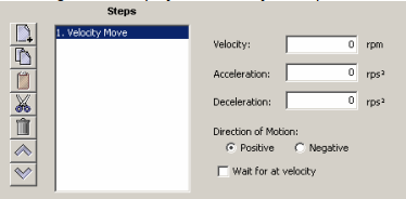
Choose appropriate values for the following parameters. Enter numeric values directly or enter the number (R0-R31) of an Indexer 2 Program register. See Using Registers to Pass Values to Function
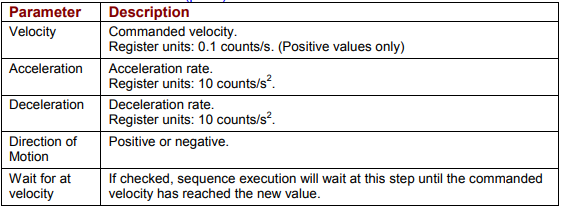
Velocity Move – parameters
| Parameter | Description |
|---|---|
| Velocity | Commanded velocity. Register units: 0.1 counts/s. (Positive values only) |
| Acceleration | Acceleration rate. Register units: 10 counts/s². |
| Deceleration | Deceleration rate. Register units: 10 counts/s². |
| Direction of Motion | Positive or negative. |
| Wait for at velocity | If checked, sequence execution will wait at this step until the commanded velocity has reached the new value. |
Original image of the table (from the PDF manual)
4.13.3 Velocity Move Position Mode Notes
Errors
A sequence error will occur if this function is executed when:
The amplifier is hardware disabled.
The amplifier is faulted.
o Motor phasing is not initialized.
o A register used for a function parameter contains a value that is not valid for the parameter.
4.14 Move
4.14.1 Move Function Overview
The Move function executes a profile move using the specified parameters.
4.14.2 Adding a Move Step to a Sequence
Click Add New Step  to open the Indexer Functions screen.
Click Move to select the function. Click Add to add it to the sequence.
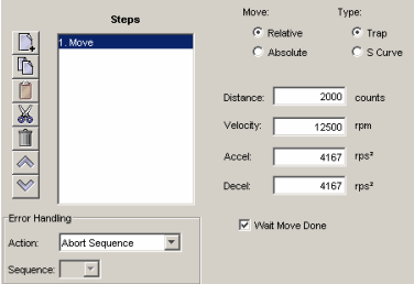
Choose appropriate values for the following parameters. Enter number values directly or enter the number (R0-R31) of an Indexer 2 Program register. See Using Registers to Pass Values to Functions
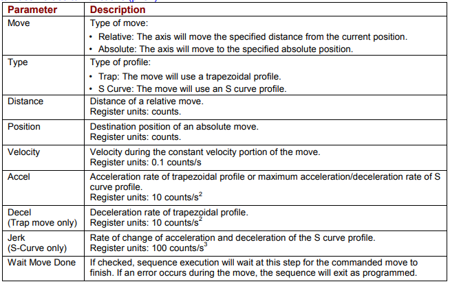
Move – parameters
| Parameter | Description |
|---|---|
| Move | Type of move: Relative – the axis will move the specified distance from the current position; Absolute – the axis will move to the specified absolute position. |
| Type | Type of profile: Trap – the move will use a trapezoidal profile; S Curve – the move will use an S curve profile. |
| Distance | Distance of a relative move. Register units: counts. |
| Position | Destination position of an absolute move. Register units: counts. |
| Velocity | Velocity during the constant velocity portion of the move. Register units: 0.1 counts/s. |
| Accel | Acceleration rate of trapezoidal profile or maximum acceleration/deceleration rate of S curve profile. Register units: 10 counts/s². |
| Decel (Trap move only) | Deceleration rate of trapezoidal profile. Register units: 10 counts/s². |
| Jerk (S-Curve only) | Rate of change of acceleration and deceleration of the S curve profile. Register units: 100 counts/s³. |
| Wait Move Done | If checked, sequence execution will wait at this step for the commanded move to finish. If an error occurs during the move, the sequence will exit as programmed. |
Original image of the table (from the PDF manual)
4.14.3 Move Function Notes
Wait Move Done
If Wait Move Done is not checked and a second move is commanded, the second move executes immediately with the following results:
If the second move is a relative, trapezoidal move, the axis moves the relative distance from where the axis was when the second move was executed.
If the second move is an absolute, trapezoidal move, the axis moves to the position specified by the second move.
If an S curve profile move is executed while another move is still in progress, an error occurs.
Errors
A sequence error will occur if:
The amplifier is hardware disabled when the Move begins, or becomes hardware disabled during the Move.
The amplifier has a fault when the move begins or a fault occurs during the move.
A software travel limit is reached or a hardware limit switch is activated during the move.
4.15 Home
4.15.1 Home Function Overview
The Home function executes a home command using the method and parameters specified.
4.15.2 Adding a Home Function Step to a Sequence
Click Add New Step  to open the Indexer Functions screen.
Click Home to select the function. Click Add to add it to the sequence.
The Program tab displays the Home function parameters.
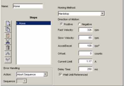
Choose appropriate values for the following parameters. Enter number values directly or enter the number (R0-R31) of an Indexer 2 Program register. See Using Registers to Pass Values to Functions
Home – parameters
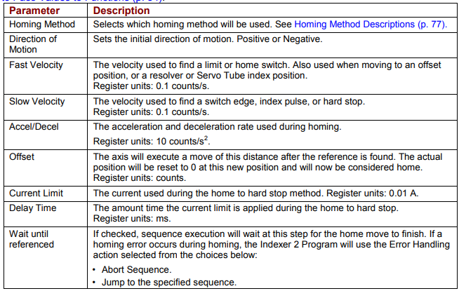
| Parameter | Description |
|---|---|
| Homing Method | Selects which homing method will be used. See Homing Method Descriptions (Appendix B). |
| Direction of Motion | Sets the initial direction of motion. Positive or Negative. |
| Fast Velocity | The velocity used to find a limit or home switch. Also used when moving to an offset position, or a resolver or Servo Tube index position. Register units: 0.1 counts/s. |
| Slow Velocity | The velocity used to find a switch edge, index pulse, or hard stop. Register units: 0.1 counts/s. |
| Accel/Decel | The acceleration and deceleration rate used during homing. Register units: 10 counts/s². |
| Offset | The axis will execute a move of this distance after the reference is found. The actual position will be reset to 0 at this new position and will now be considered home. Register units: counts. |
| Current Limit | The current used during the home to hard stop method. Register units: 0.01 A. |
| Delay Time | The amount time the current limit is applied during the home to hard stop. Register units: ms. |
| Wait until referenced | If checked, sequence execution will wait at this step for the home move to finish. If a homing error occurs during homing, the Indexer 2 Program will use the Error Handling action selected from the choices: Abort Sequence, or Jump to the specified sequence. |
Original image of the table (from the PDF manual)
4.15.3 Home Function Notes
Do not execute a move function until the homing function is complete.
Errors
A sequence error will occur if:
The amplifier is, or becomes, hardware disable during the Homing function.
The amplifier has a fault at the beginning of the Home function or a fault occurs during the function.
Other sequence errors may occur that are specific to the homing method selected. See Homing Method Descriptions.
4.16 Current Move
4.16.1 Current Move Function Overview
This function is used to change the operating mode of the amplifier to programmed current mode and configure the mode.
4.16.2 Adding a Current Move Step to a Sequence
Click Add New Step  on the Program tab to open Indexer Functions.
Click Motion:Current Move to select the function. Click Add to add it to the sequence.
The Program tab displays the Current Move parameters.
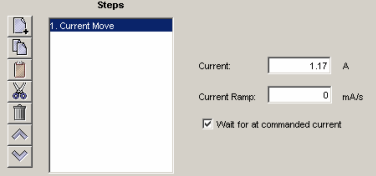
Choose appropriate values for the following parameters. Enter numeric values directly or enter the number (R0-R31) of an Indexer 2 Program register. See Using Registers to Pass Values to Functions
Current Move – parameters
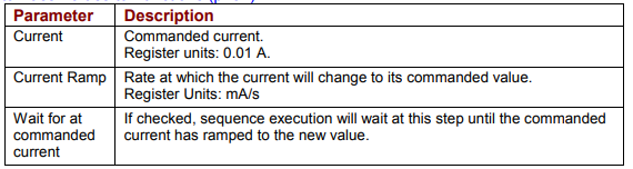
| Parameter | Description |
|---|---|
| Current | Commanded current. Register units: 0.01 A. |
| Current Ramp | Rate at which the current will change to its commanded value. Register Units: mA/s. |
| Wait for at commanded current | If checked, sequence execution will wait at this step until the commanded current has ramped to the new value. |
Original image of the table (from the PDF manual)
4.16.3 Current Move Notes
Errors
A sequence error will occur if this function is executed when:
The amplifier is hardware disabled.
The amplifier is faulted.
Motor phasing is not initialized.
A register used for a function parameter contains a value that is not valid for the parameter.
4.17 Velocity Move Velocity Mode
4.17.1 Velocity Move Velocity Mode Function Overview
This function is used to change the operating mode of the amplifier to programmed velocity mode and configures a constant velocity trajectory.
4.17.2 Adding a Velocity Move Velocity Mode Step to a Sequence
Click Add New Step  on the Program tab to open Indexer Functions.
Click Motion:Velocity Move Velocity Mode to select the function. Click Add to add it to the sequence.
The Program tab displays the Velocity Move parameters.
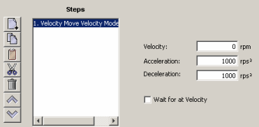
Choose appropriate values for the following parameters. Enter numeric values directly or enter the number (R0-R31) of an Indexer 2 Program register. See Using Registers to Pass Values to Functions
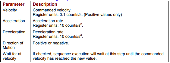
Velocity Move – parameters
| Parameter | Description |
|---|---|
| Velocity | Commanded velocity. Register units: 0.1 counts/s. (Positive values only) |
| Acceleration | Acceleration rate. Register units: 10 counts/s². |
| Deceleration | Deceleration rate. Register units: 10 counts/s². |
| Direction of Motion | Positive or negative. |
| Wait for at velocity | If checked, sequence execution will wait at this step until the commanded velocity has reached the new value. |
Original image of the table (from the PDF manual)
4.17.3 Velocity Move Velocity Mode Notes
Errors
A sequence error will occur if this function is executed when:
The amplifier is hardware disabled.
The amplifier is faulted.
Motor phasing is not initialized.
A register used for a function parameter contains a value that is not valid for the parameter.
4.18 Analog Velocity Mode
4.18.1 Analog Velocity Mode Function Overview
This function is used to change the operating mode of the amplifier to analog velocity mode and configure the mode.
4.18.2 Adding an Analog Velocity Mode Step to a Sequence
Click Add New Step  on the Program tab to open Indexer Functions.
Click Mode:Analog Velocity Mode to select the function. Click Add to add it to the sequence.
The Program tab displays the Analog Velocity Mode parameters.
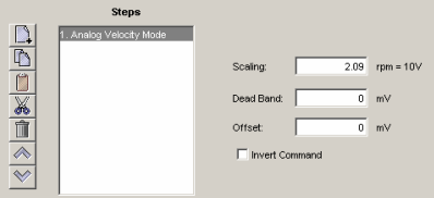
Choose appropriate values for the following parameters. Enter numeric values directly or enter the number (R0-R31) of an Indexer 2 Program register. See Using Registers to Pass Values to Functions
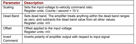
Analog Velocity Mode – parameters
| Parameter | Description |
|---|---|
| Scaling | Sets the input-voltage to-velocity command ratio. Register units: Counts / second = 10 V. |
| Dead Band | Sets dead band. The amplifier treats anything within the dead band ranges as zero, and subtracts the dead band value from all other values. Register units: mV. |
| Offset | Offset applied to the input voltage. Register units: mV. |
| Invert Command | Inverts polarity of amplifier output with respect to input signal. |
Original image of the table (from the PDF manual)
4.18.3 Analog Velocity Mode Notes
Errors
A sequence error will occur if this function is executed when:
The amplifier is hardware disabled.
The amplifier is faulted.
Motor phasing is not initialized.
A register used for a function parameter contains a value that is not valid for the parameter.
4.19 Analog Position Mode
4.19.1 Analog Position Mode Function Overview
This function is used to change the operating mode of the amplifier to Analog Position mode and configure the mode.
4.19.2 Adding an Analog Position Mode Step to a Sequence
Click Add New Step  on the Program tab to open Indexer Functions.
Click Mode: Analog Position Mode to select the function. Click Add to add it to the sequence.
The Program tab displays the Analog Position Mode parameters.
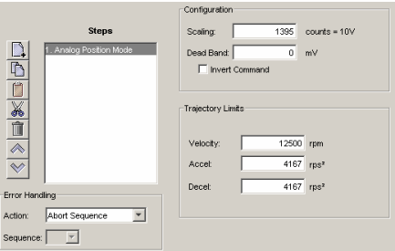
Choose appropriate values for the following parameters. Enter numeric values directly or enter the number (R0-R31) of an Indexer 2 Program register. See Using Registers to Pass Values to Functions
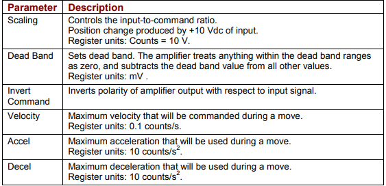
Analog Position Mode – parameters
| Parameter | Description |
|---|---|
| Scaling | Controls the input-to-command ratio. Position change produced by +10 Vdc of input. Register units: Counts = 10 V. |
| Dead Band | Sets dead band. The amplifier treats anything within the dead band ranges as zero, and subtracts the dead band value from all other values. Register units: mV. |
| Invert Command | Inverts polarity of amplifier output with respect to input signal. |
| Velocity | Maximum velocity that will be commanded during a move. Register units: 0.1 counts/s. |
| Accel | Maximum acceleration that will be used during a move. Register units: 10 counts/s². |
| Decel | Maximum deceleration that will be used during a move. Register units: 10 counts/s². |
Original image of the table (from the PDF manual)
4.19.3 Analog Position Mode Notes
The analog position command operates as a relative motion command. When the amplifier is enabled the voltage on the analog input is read. Then, any change in the command voltage will move the axis a relative distance, proportional as programmed to the change in voltage, from its position when enabled.
To use the analog position command as an absolute position command, the amplifier should be homed every time it is enabled. A simple way to accomplish this is to program the priority sequence to use the same input as the enable input. The priority sequence would be programmed to home the axis. In this way, the axis will be automatically homed every time the amplifier is enabled.
Errors
A sequence error will occur if this function is executed when:
The amplifier is hardware disabled.
The amplifier is faulted.
Motor phasing is not initialized.
A register used for a function parameter contains a value that is not valid for the parameter.
4.20 Disable Amplifier
4.20.1 Disable Amplifier Function Overview
This function is used to software disable the amplifier.
4.20.2 Adding an Disable Amplifier Step to a Sequence
Click Add New Step  on the Program tab to open Indexer Functions.
Click Mode: Disable Amplifier to select the function. Click Add to add it to the sequence.
4.20.3 Disable Amplifier Notes
The amplifier will automatically re-enable with the execution of any function, such as Home or Move, which requires axis motion.
Errors
This function does not generate an error.
4.21 Camming Internal Master
4.21.1 Camming Internal Master Function Overview
This function is used to change the velocity of the Camming Internal Master.
4.21.2 Adding a Camming Internal Master Step to a Sequence
Click Add New Step  on the Program tab to open Indexer Functions.
Click Mode: Camming Internal Master to select the function. Click Add to add it to the sequence.
The Program tab displays the Camming Internal Master settings.
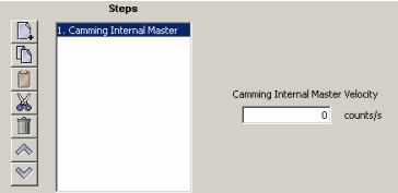
Choose appropriate values for the following parameter. Enter the velocity directly or
enter the number (R0-R31) of an Indexer 2 Program register. See Using Registers to
Pass Values to Functions
Camming Internal Master – parameters
| Parameter | Description |
|---|---|
| Velocity | Velocity of the Camming Internal Master. Register units: 0.1 counts/s. |
Original image of the table (from the PDF manual)

4.21.3 Camming Internal Master Function Notes
Errors
A sequence error will occur if this function is executed when a register used for a function parameter contains a value that is not valid for the parameter.
4.22 Camming
4.22.1 Camming Function Overview
This function is used to change the operating mode of the amplifier to Camming and to configure the Camming mode.
4.22.2 Adding a Camming Step to a Sequence
Click Add New Step  on the Program tab to open Indexer Functions.
Click Mode: Camming to select the function. Click Add to add it to the sequence.
The Program tab displays the Camming mode settings.
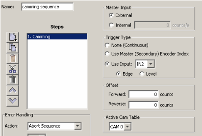
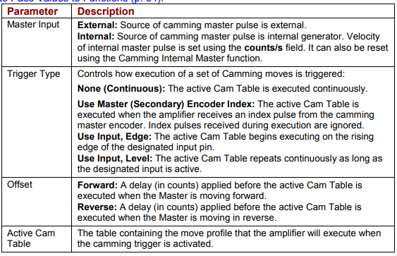
Choose appropriate values for the following parameters. Enter numeric values directly or enter the number (R0-R31) of an Indexer 2 Program register. See Using Registers to Pass Values to Functions
Camming – parameters
| Parameter | Description |
|---|---|
| Master Input | External: Source of camming master pulse is external. Internal: Source of camming master pulse is internal generator. Velocity of internal master pulse is set using the counts/s field. It can also be reset using the Camming Internal Master function. |
| Trigger Type | Controls how execution of a set of Camming moves is triggered. None (Continuous): The active Cam Table is executed continuously. Use Master (Secondary) Encoder Index: The active Cam Table is executed when the amplifier receives an index pulse from the camming master encoder. Index pulses received during execution are ignored. Use Input, Edge: The active Cam Table begins executing on the rising edge of the designated input pin. Use Input, Level: The active Cam Table repeats continuously as long as the designated input is active. |
| Offset | Forward: A delay (in counts) applied before the active Cam Table is executed when the Master is moving forward. Reverse: A delay (in counts) applied before the active Cam Table is executed when the Master is moving in reverse. |
| Active Cam Table | The table containing the move profile that the amplifier will execute when the camming trigger is activated. |
Original image of the table (from the PDF manual)
4.22.3 Camming Function Notes
The velocity of internal master pulse can be changed using the Camming Internal Master function.
The amplifier will stay in the camming mode of operation until another Indexer 2 Program function changes it or the amplifier is reset or power cycled.
Errors
A sequence error will occur if this function is executed when:
The amplifier is hardware disabled.
The amplifier is faulted.
Motor phasing is not initialized.
A register used for a function parameter contains a value that is not valid for the parameter.
4.23 Digital Position Mode
4.23.1 Digital Position Mode Function Overview
Change the operating mode of the amplifier to Digital Position mode and configure the mode.
4.23.2 Adding an Digital Position Mode Step to a Sequence
Click Add New Step  on the Program tab to open Indexer Functions.
Click Mode:Digital Position Mode to select the function. Click Add to add it to the sequence.
The Program tab displays the Digital Position Mode parameters.
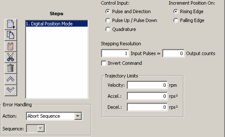
Choose appropriate values for the following parameters. Enter numeric values directly
or enter the number (R0-R31) of an Indexer 2 Program register. See Using Registers
to Pass Values to Functions
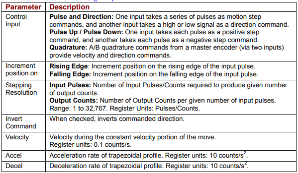
Digital Position Mode – parameters
| Parameter | Description |
|---|---|
| Control Input | Pulse and Direction: One input takes a series of pulses as motion step commands, and another input takes a high or low signal as a direction command. Pulse Up / Pulse Down: One input takes each pulse as a positive step command, and another takes each pulse as a negative step command. Quadrature: A/B quadrature commands from a master encoder (via two inputs) provide velocity and direction commands. |
| Increment position on | Rising Edge: Increment position on the rising edge of the input pulse. Falling Edge: Increment position on the falling edge of the input pulse. |
| Stepping Resolution | Input Pulses: Number of Input Pulses/Counts required to produce given number of output counts. Output Counts: Number of Output Counts per given number of input pulses. Range: 1 to 32,767. Register Units: Pulses/Counts. |
| Invert Command | When checked, inverts commanded direction. |
| Velocity | Velocity during the constant velocity portion of the move. Register units: 0.1 counts/s. |
| Accel | Acceleration rate of trapezoidal profile. Register units: 10 counts/s². |
| Decel | Deceleration rate of trapezoidal profile. Register units: 10 counts/s². |
Original image of the table (from the PDF manual)
4.23.3 Digital Position Mode Notes
Errors
A sequence error will occur if this function is executed when:
The amplifier is hardware disabled.
The amplifier is faulted.
Motor phasing is not initialized.
A register used for a function parameter contains a value that is not valid for the parameter.
4.24 Velocity Loop Single Pole Output Filter
4.24.1 Velocity Loop Single Pole Output Filter Function Overview
This function modifies the Velocity Loop Output Filter.
4.24.2 Adding a Velocity Loop Single Pole Output Filter Step to a Sequence
Click Add New Step  on the Program tab to open Indexer Functions.
Click Filters:Velocity Loop Single Pole Output Filter to select the function. Click
Add to add it to the sequence.
The Program tab displays the Filter parameters.
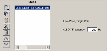
Enter a Cut Off Frequency value of between 1 and 1500.
4.24.3 Velocity Loop Single Pole Output Filter Notes
Errors
This function does not generate sequence errors.
Słowa kluczowe
Move, Velocity Move, Home, Current Move, Analog Velocity Mode, Analog Position Mode, Disable Amplifier, Camming, Cam Table, Digital Position Mode, pulse and direction, quadrature, trapezoidal, S-curve