5. Mapping Data into the Image Table
Streszczenie: Mapowanie danych wejściowych do obrazu procesu: moduły 4-kanałowe (bity 0–3 bajtu 0, bity 4–7 zarezerwowane), 8-kanałowe (bajt 0) i 16-kanałowe (bajty 0 i 1).
EN: Mapping input data into the process image for 4-, 8- and 16-channel modules.
Dotyczy: moduły wejść cyfrowych CREVIS serii ST-1xxx systemu FnIO (4, 8 i 16 wejść; 5, 12/24, 48 Vdc oraz 110/220 Vac)
Źródło: dokumentacja producenta (CREVIS ST-1xxx Digital Input Modules User Manual); tabele przepisane z obrazów na tekst – opracowanie Multiprojekt
5.1.1 ST-1xx4
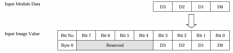
Input module data D3–D0 are mapped to the input image as follows:
ST-1xx4 – input image value
| Bit
| Bit 7 | Bit 6 | Bit 5 | Bit 4 | Bit 3 | Bit 2 | Bit 1 | Bit 0 |
|---|---|---|---|---|---|---|---|---|
| Byte 0 | Reserved | Reserved | Reserved | Reserved | D3 | D2 | D1 | D0 |
5.2.2 ST-1xx8
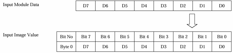
Input module data D7–D0 are mapped to the input image as follows:
ST-1xx8 – input image value
| Bit
| Bit 7 | Bit 6 | Bit 5 | Bit 4 | Bit 3 | Bit 2 | Bit 1 | Bit 0 |
|---|---|---|---|---|---|---|---|---|
| Byte 0 | D7 | D6 | D5 | D4 | D3 | D2 | D1 | D0 |
5.3.3 ST-1xxF
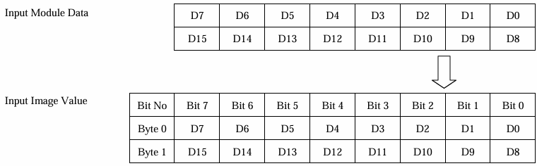
Input module data D15–D0 are mapped to the input image as follows:
ST-1xxF – input image value
| Bit No | Bit 7 | Bit 6 | Bit 5 | Bit 4 | Bit 3 | Bit 2 | Bit 1 | Bit 0 |
|---|---|---|---|---|---|---|---|---|
| Byte 0 | D7 | D6 | D5 | D4 | D3 | D2 | D1 | D0 |
| Byte 1 | D15 | D14 | D13 | D12 | D11 | D10 | D9 | D8 |
Słowa kluczowe