
2. 17-Pin Interface Description
Streszczenie: Definicja pinów 17-pinowego złącza M12 czytnika ID3000 (zasilanie, wejścia DI_0–DI_2, wyjścia DO_0–DO_2, RS-232, Fast Ethernet) oraz dołączony kabel 17-pin z końcówkami RJ45 i DB9.
EN: ID3000 17-pin M12 interface pin definitions (power, DI_0–DI_2 inputs, DO_0–DO_2 outputs, RS-232, Fast Ethernet) and the supplied 17-pin cable with RJ45 and DB9 ends.
Dotyczy: przemysłowy czytnik kodów Hikrobot serii ID3000 (złącze M12 17-pin, Fast Ethernet, RS-232; obsługa przez klienta IDMVS)
Źródło: dokumentacja producenta (Hikrobot ID3000 Series Industrial Code Reader User Manual, V3.1.0); tabele i uwagi przepisane z obrazów na tekst, opisy rysunków – opracowanie Multiprojekt
Read the following section to get pin definitions of 17-pin M12 interface.
Pin Definitions
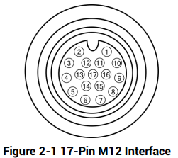
Figure 2-1 17-Pin M12 Interface
Figure description (text version): Front view of the 17-pin M12 connector with the coding key at the top. Pins 1–10 are on the outer ring (1 and 2 next to the key, then counter-clockwise 3–10), pins 11–16 on the inner ring and pin 17 in the centre.
Table 2-1 Pin Definitions
| No. | Signal | I/O Signal Source | Description |
|---|---|---|---|
| 1 | POWER_IN | – | Direct current power supply positive |
| 2 | DO_2 | LineOut5 signal line | Non-isolated output |
| 3 | Reserved | – | – |
| 4 | RS232TX | – | RS-232 serial port output |
| 5 | RS232RX | – | RS-232 serial port input |
| 6 | MDI0+ | – | Fast Ethernet signal MDI0+ |
| 7 | MDI1- | – | Fast Ethernet signal MDI1- |
| 8 | DO_0 | LineOut4 signal line | Non-isolated output |
| 9 | DI_2 | LineIn2 signal line | Non-isolated input |
| 10 | DO_1 | LineOut3 signal line | Non-isolated output |
| 11 | GND | Signal ground | Direct current power supply negative |
| 12 | Reserved | – | – |
| 13 | Reserved | – | – |
| 14 | MDI0- | – | Fast Ethernet signal MDI0- |
| 15 | MDI1+ | – | Fast Ethernet signal MDI1+ |
| 16 | DI_0 | LineIn0 signal line | Non-isolated input |
| 17 | DI_1 | LineIn1 signal line | Non-isolated input |
17-Pin Cable
Note:
- You should refer to the table above and the label attached to the supplied 17-pin cable to wire the device.
- Some devices, due to different firmware versions, may have output signal source of LineOut0/1/2. Refer to the device you purchased for actual conditions.
- The 12th pin of some devices is input signal connecting pull-up and pull-down resistor, and you should wire the device accordingly.
- It is recommended to use the supplied 17-pin cable, as shown below. The 6th, 7th, 14th, and 15th pin have been made as RJ45 connector. The lines of other pins should be wired according to the actual demands.
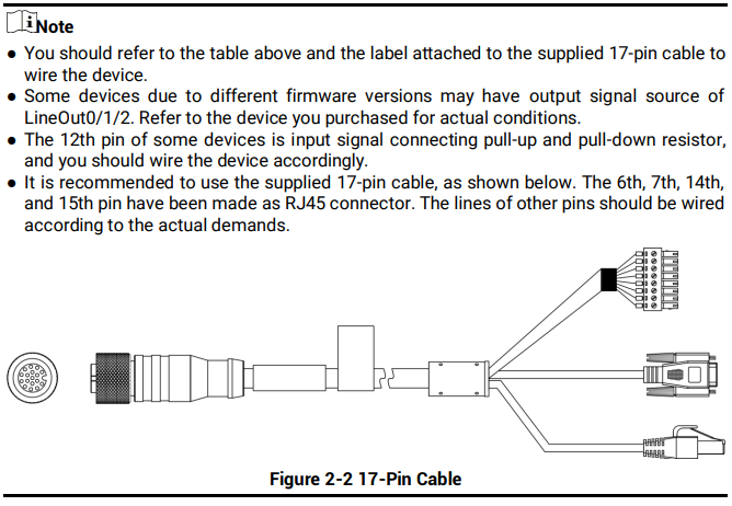
Figure 2-2 17-Pin Cable
Słowa kluczowe
Hikrobot ID3000, 17-pin, M12, pinout, pin definitions, POWER_IN, GND, DI_0, DI_1, DI_2, DO_0, DO_1, DO_2, LineIn, LineOut, RS232TX, RS232RX, MDI, Fast Ethernet, RJ45, 17-pin cable