
2. Product Information – Part 2 (Dimensions and Maintenance)
Streszczenie: Informacje o produkcie KE300 (część 2 z 2): budowa falownika, wymiary zewnętrzne i montażowe dla wszystkich mocy, wymiary panelu, konserwacja okresowa i gwarancja.
EN: KE300 product information (part 2 of 2): inverter parts, external and mounting dimensions for all power ratings, keypad dimensions, routine maintenance and warranty.
Dotyczy: falownik wektorowy Micno KE300 (zasilanie 1AC/3AC 220 V, 3AC 380 V, 3AC 660 V; moce 0,4–630 kW)
Źródło: dokumentacja producenta (Micno KE300 Series Inverter User Manual); tabele przepisane z obrazów na tekst, opisy rysunków – opracowanie Multiprojekt
Nawigacja: część 2 z 2 · poprzednia: ← poprzednia część (Part 1 (Model and Specifications))
2.6 External & Installation Dimensions
2.6.1 Parts Description
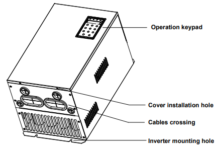
Diagram description (text version): Parts of a small-frame KE300 inverter (isometric view): operation keypad on the front cover, cover installation hole, cable crossing (cable entry openings at the bottom) and inverter mounting holes.
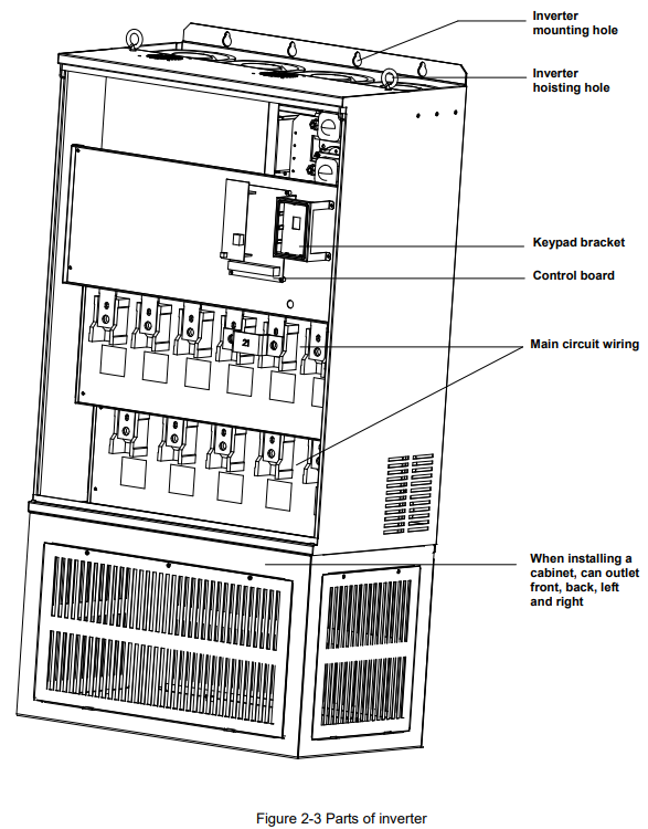
Diagram description (text version): Figure 2-3 Parts of inverter (large frame, front cover removed): inverter mounting holes and hoisting (lifting) holes at the top, keypad bracket, control board, and main circuit wiring terminals in two rows. The cabinet-type base below can have cable outlets at the front, back, left and right when installing in a cabinet.
2.6.2 External & Installation Dimensions
1AC/3AC 220V 0.4–2.2 kW Inverter Dimension
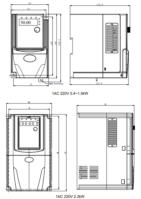
Diagram description (text version): Front and side dimension drawings of 1AC/3AC 220V 0.4–2.2 kW inverters. 0.4–1.5 kW: width 78 mm (mounting hole spacing 73 mm), height 140/148.4 mm (hole spacing 128 mm), depth 124.8/121.8 mm, M4 grounding screw. 2.2 kW: dimensions W, H, D and mounting spacing A, B as given in the table below.
| Power range | W (mm) | H/H1 (mm) | D/D1 (mm) | A (mm) | B (mm) | Mounting bolt model |
|---|---|---|---|---|---|---|
| 0.4 ~ 1.5 kW | 78 | 140/148.4 | 124.8/121.8 | 73 | 128 | M4 |
| 2.2 kW | 110 | 185 | 153 | 98 | 174 | M4 |
W, H/H1, D/D1 – external dimensions; A, B – installation dimensions.
3AC 220V 4 kW and Above Inverter Dimension
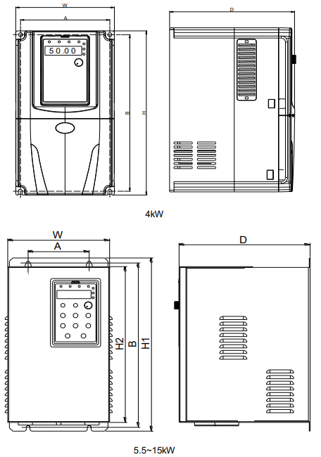
Diagram description (text version): Front and side dimension drawings of 3AC 220V inverters from 4 kW (plastic housing, dimensions W, H, D, A, B) and 5.5–15 kW (metal housing with keypad, dimensions W, A, H1, H2, B, D). The values for each power range are given in the table below.
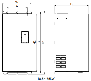
Diagram description (text version): Front and side dimension drawing of 3AC 220V 18.5–75 kW inverters (cabinet with three mounting holes at the top): width W, mounting spacing A, heights H1, H2, B and depth D – values in the table below.
3AC 220V inverter dimensions
| Power range | W (mm) | H1 (mm) | H2 (mm) | D (mm) | A (mm) | B (mm) | Mounting bolt model |
|---|---|---|---|---|---|---|---|
| 4 kW | 135 | 240 | 240 | 173 | 122.6 | 229 | M4 |
| 5.5 ~ 7.5 kW | 200 | 329.1 | 300 | 177.2 | 90 | 316.6 | M4 |
| 11 ~ 15 kW | 255 | 439.6 | 402.4 | 209.6 | 140 | 423.6 | M5 |
| 18.5 ~ 22 kW | 280 | 570 | 521.2 | 258 | 190 | 552 | M6 |
| 30 ~ 37 kW | 320 | 600 | 552 | 330 | 230 | 582 | M8 |
| 45 ~ 55 kW | 320 | 715 | 662 | 330 | 230 | 695.5 | M8 |
| 75 kW | 480 | 790 | 725 | 385 | 360 | 768 | M10 |
W, H1, H2, D – external dimensions; A, B – installation dimensions.
For 4 kW the source gives a single height of 240 mm (H1 = H2).
3AC 380V Inverter Dimension
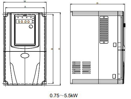
Diagram description (text version): Front and side dimension drawing of 3AC 380V 0.75–5.5 kW inverters (plastic housing with keypad): width W, mounting spacing A, height H, mounting spacing B and depth D – values in the 3AC 380V dimension table.
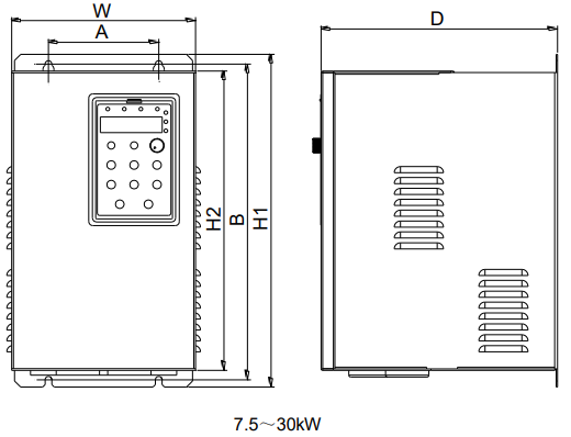
Diagram description (text version): Front and side dimension drawing of 3AC 380V 7.5–30 kW inverters (metal housing with keypad, two top mounting holes): width W, mounting spacing A, heights H1, H2, B and depth D – values in the 3AC 380V dimension table.
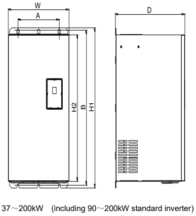
Diagram description (text version): Front and side dimension drawing of 3AC 380V 37–200 kW inverters (including 90–200 kW standard version, wall-mounted metal cabinet with three top mounting holes): width W, mounting spacing A, heights H1, H2, B and depth D – values in the 3AC 380V dimension table.
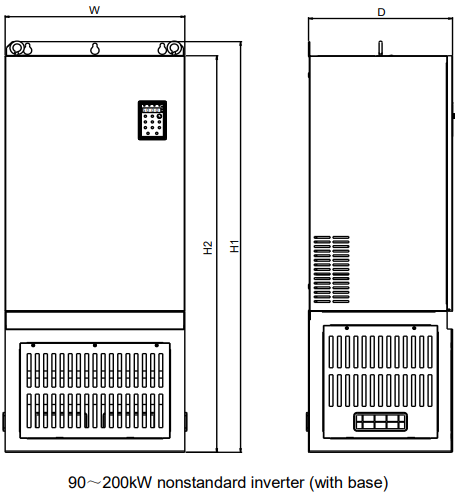
Diagram description (text version): Front and side dimension drawing of the 90–200 kW non-standard inverter version with a floor base (ventilated base under the cabinet, lifting eyes at the top): width W, heights H1 (with base) and H2 (cabinet), depth D – values in the 3AC 380V dimension table.
3AC 380V inverter dimensions (0.75–200 kW)
| Power range | W (mm) | H1 (mm) | H2 (mm) | D (mm) | A (mm) | B (mm) | Mounting bolt model |
|---|---|---|---|---|---|---|---|
| 0.75 ~ 2.2 kW | 110 | 185 | 185 | 153 | 98 | 174 | M4 |
| 3.7 ~ 5.5 kW | 135 | 240 | 240 | 173 | 122.6 | 229 | M4 |
| 7.5 kW | 170 | 314 | 285 | 167 | 90 | 301.6 | M4 |
| 11 ~ 15 kW | 200 | 329.1 | 300 | 177.2 | 90 | 316.6 | M4 |
| 18.5 ~ 30 kW | 255 | 439.6 | 402.4 | 209.6 | 140 | 423.6 | M5 |
| 37 ~ 45 kW | 280 | 570 | 521.2 | 258 | 190 | 552 | M6 |
| 55 ~ 75 kW | 320 | 600 | 552 | 330 | 230 | 582 | M8 |
| 90 ~ 110 kW (without base) | 320 | 715 | 662 | 330 | 230 | 695.5 | M8 |
| 90 ~ 110 kW (with base) | 320 | 992 | 962 | 330 | – | – | – |
| 132 ~ 200 kW (without base) | 480 | 790 | 725 | 385 | 360 | 768 | M10 |
| 132 ~ 200 kW (with base) | 480 | 1165 | 1125 | 385 | – | – | – |
W, H1, H2, D – external dimensions; A, B – installation dimensions.
For 0.75–5.5 kW the source gives a single height (H1 = H2).
Note: Base is optional for 90–200 kW inverters. Standard inverters are without base.
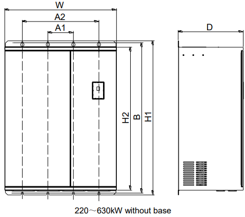
Diagram description (text version): Front and side dimension drawing of 3AC 380V 220–630 kW inverters without base (large cabinet with four top mounting holes): width W, mounting spacings A1 and A2, heights H1, H2, B and depth D – values in the table for 220–630 kW.
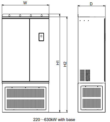
Diagram description (text version): Front and side dimension drawing of 3AC 380V 220–630 kW inverters with floor base (ventilated base under the cabinet): width W, heights H1 and H2, depth D – values in the table below.
3AC 380V inverter dimensions (220–630 kW)
| Power range | W (mm) | H1 (mm) | H2 (mm) | D (mm) | A1 (mm) | A2 (mm) | B (mm) | Mounting bolt model |
|---|---|---|---|---|---|---|---|---|
| 220 ~ 315 kW (without base) | 700 | 970 | 900 | 408 | 160 | 480 | 946 | M10 |
| 220 ~ 315 kW (with base) | 700 | 1390 | 1350 | 408 | – | – | – | – |
| 350 ~ 630 kW (without base) | 940 | 1140 | 1100 | 458 | 240 | 660 | 1146 | M10 |
| 350 ~ 630 kW (with base) | 940 | 1690 | 1650 | 458 | – | – | – | – |
W, H1, H2, D – external dimensions; A1, A2, B – installation dimensions.
3AC 660V Inverter Dimension
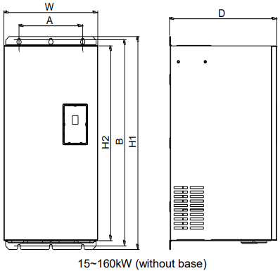
Diagram description (text version): Front and side dimension drawing of 3AC 660V 15–160 kW inverters without base (wall-mounted cabinet with three top mounting holes): width W, mounting spacing A, heights H1, H2, B and depth D – values in the 3AC 660V dimension table.
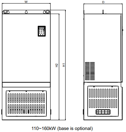
Diagram description (text version): Front and side dimension drawing of 3AC 660V 110–160 kW inverters with the optional floor base: width W, heights H1 (with base) and H2 (cabinet), depth D – values in the table below.
3AC 660V inverter dimensions
| Power range | W (mm) | H1 (mm) | H2 (mm) | D (mm) | A (mm) | B (mm) | Mounting bolt model |
|---|---|---|---|---|---|---|---|
| 15 ~ 37 kW (without base) | 280 | 650 | 601 | 333 | 290 | 631.5 | M6 |
| 45 ~ 90 kW (without base) | 320 | 808 | 754 | 356 | 230 | 780 | M8 |
| 110 ~ 160 kW (without base) | 480 | 790 | 725 | 385 | 360 | 768 | M10 |
| 110 ~ 160 kW (with base) | 480 | 1165 | 1125 | 385 | – | – | – |
W, H1, H2, D – external dimensions; A, B – installation dimensions.
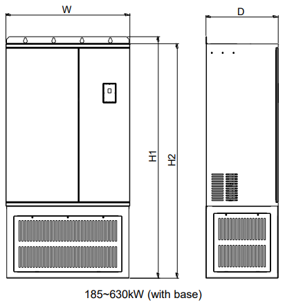
Diagram description (text version): Front and side dimension drawing of 3AC 660V 185–630 kW inverters with floor base (double-door cabinet, four top mounting holes): width W, heights H1 and H2, depth D – values in the table below.
3AC 660V inverter dimensions (185–630 kW)
| Power range | W (mm) | H1 (mm) | H2 (mm) | D (mm) | A1 (mm) | A2 (mm) | B (mm) | Mounting bolt model |
|---|---|---|---|---|---|---|---|---|
| 185 ~ 250 kW (without base) | 700 | 970 | 900 | 408 | 160 | 480 | 946 | M10 |
| 185 ~ 250 kW (with base) | 700 | 1390 | 1350 | 408 | – | – | – | – |
| 280 ~ 630 kW (without base) | 940 | 1140 | 1100 | 458 | 240 | 660 | 1146 | M10 |
| 280 ~ 630 kW (with base) | 940 | 1690 | 1650 | 458 | – | – | – | – |
W, H1, H2, D – external dimensions; A1, A2, B – installation dimensions.
2.6.3 Keypad External Dimension
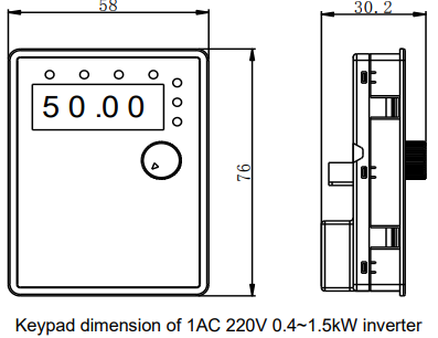
Diagram description (text version): Keypad dimension of the 1AC 220V 0.4–1.5 kW inverter: front view 58 mm wide × 76 mm high, side view depth 30.2 mm (4-digit LED display with status LEDs and a potentiometer knob).
Illustration: This keypad can be connected with the inverter externally by ordinary network cable, also can be mounted on the front side of panel directly. The suggested thickness of panel is 1.2mm.
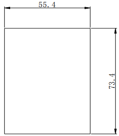
Diagram description (text version): Panel cut-out for mounting the keypad on the front side of a panel: rectangular opening 55.4 mm wide × 73.4 mm high (suggested panel thickness 1.2 mm).
The installation size on the panel while using this keypad
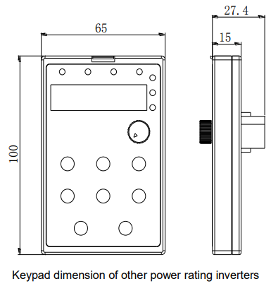
Diagram description (text version): Keypad dimension of the other power rating inverters: front view 65 mm wide × 100 mm high (LED display, status LEDs, potentiometer knob and 8 keys), side view depth 27.4 mm, of which 15 mm is the front part.
Illustration: This keypad can be connected with the inverter externally by ordinary network cable, and it needs an additional bracket to fix it.
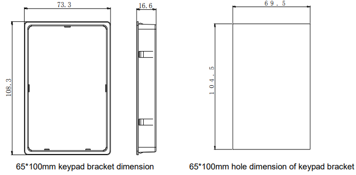
Diagram description (text version): Left: 65×100 mm keypad bracket dimension – 73.3 mm wide × 108.3 mm high, depth 16.6 mm. Right: panel hole (cut-out) dimension for the keypad bracket – 69.5 mm wide × 104.5 mm high.
2.7 Routine Maintenance of Inverter
2.7.1 Routine Maintenance
The influence of the ambient temperature, humidity, dust and vibration will cause the aging of the devices in the inverter, which may cause potential fault of the inverter or reduce the service life of the inverter.
Therefore, it is necessary to carry out routine and periodical maintenance on the inverter.
Routine inspection Items include:
- Whether there is any abnormal change in the running sound of the motor;
- Whether the motor has vibration during the running;
- Whether there is any change to the installation environment of the inverter;
- Whether the inverter cooling fan works normally;
- Whether the inverter has over temperature.
Routine cleaning:
- The inverter should be kept clean all the time.
- The dust on the surface of the inverter should be effectively removed, so as to prevent the dust entering the inverter. Especially the metal dust is not allowed.
- The oil stain on the inverter cooling fan should be effectively removed.
2.7.2 Periodic Inspection
Please perform periodic inspection on the places where the inspection is a difficult thing.
Periodic inspection Items include:
- Check and clean the air duct periodically;
- Check if the screws are loose;
- Check if the inverter is corroded;
- Check if the wire connector has arc signs;
- Main circuit insulation test.
Remainder: When using the megameter (DC 500V megameter recommended) to measure the insulating resistance, the main circuit should be disconnected with the inverter. Do not use the insulating resistance meter to test the insulation of control circuit. It is not necessary to conduct the high voltage test (which has been completed upon delivery).
2.7.3 Replacement of Vulnerable Parts for Inverter
The vulnerable parts of the inverter include cooling fan and filter electrolytic capacitor, whose service life depends on the operating environment and maintenance status. General service life is shown as follows:
| Part name | Service life |
|---|---|
| Fan | 2 ~ 3 years |
| Electrolytic capacitor | 4 ~ 5 years |
The user can determine the year of replacement according to the operating time.
1) Cooling fan
Possible reason for damage: Bearing is worn and blade is aging.
Judging criteria: Whether there is crack on the blade and whether there is abnormal vibration noise upon startup.
2) Filter electrolytic capacitor
Possible reason for damage: Input power supply in poor quality, high ambient temperature, frequent load jumping, and electrolyte aging.
Judging criteria: Whether there is liquid leakage and whether the safe valve has projected, and measure the static capacitance, and the insulating resistance.
2.7.4 Storage of Inverter
Upon acquiring the inverter, the user should pay attention to the following points regarding the temporary and long-term storage of the inverter:
- Pack the inverter with original package and place back into the packing box of our company.
- Long-term storage will degrade the electrolytic capacitor. Thus, the product should be powered up once every 2 years, each time lasting at least five hours. The input voltage should be increased slowly to the rated value with the regulator.
2.8 Instructions on Warranty of Inverter
Free warranty only applies to the inverter itself.
- MICNO provides 18 month warranty (starting from the date of original shipment as indicated on the barcode) for the failure or damage under normal use conditions. If the equipment has been used for over 18 months, reasonable repair expenses will be charged.
- Reasonable repair expenses will be charged for the following situations within 18 months:
a) The equipment is damaged because the user fails to comply with the requirements of the user’s manual;
b) Damage caused by fire, flood and abnormal voltage;
3) Damage caused when the inverter is used for abnormal function.
The service expenses will be calculated according to the standard of the manufacturer. If there is any agreement, the agreement should prevail.
Słowa kluczowe
Micno KE300, wymiary, dimensions, wymiary montażowe, installation dimensions, panel, keypad, wspornik panelu, keypad bracket, konserwacja, maintenance, wentylator, kondensator, gwarancja, warranty