
6. Parameter Description – Part 4 (Groups P5–P6)
Streszczenie: Opis parametrów KE300 (część 4 z 8): zaciski wyjściowe (HDO, przekaźniki, AO – funkcje i skalowanie) oraz sterowanie startem i zatrzymaniem (tryby startu, śledzenie prędkości, hamowanie DC, krzywe S).
EN: KE300 parameter description (part 4 of 8): output terminals (HDO, relays, AO – functions and scaling) and start/stop control (start modes, speed tracking, DC braking, S-curves).
Dotyczy: falownik wektorowy Micno KE300 (zasilanie 1AC/3AC 220 V, 3AC 380 V, 3AC 660 V; moce 0,4–630 kW)
Źródło: dokumentacja producenta (Micno KE300 Series Inverter User Manual); tabele przepisane z obrazów na tekst, opisy rysunków – opracowanie Multiprojekt
Nawigacja: część 4 z 8 · ← poprzednia część (Part 3 (Group P4)) · następna część (Part 5 (Groups P7–P8)) →
Group P5 Output Terminal
The standard Inverter has 2 multifunctional analog output terminals, 2 multifunctional relay output terminals, 1 HDO terminal (can be used as either high-speed pulse output terminal or collector open output)
| Parameter | Name | Factory default | Setting range |
|---|---|---|---|
| P5-00 | HDO terminal output selection | 0 | 0: High speed pulse output 1: Open collector output |
HDO terminal is programmable multiplexing terminal, can be used as high-speed pulse output, with maximum frequency 100.00 kHz. Refer to P5-06 for details.
Digital output function selection
| Parameter | Name | Factory default |
|---|---|---|
| P5-01 | HDO open collector output selection | 0 |
| P5-02 | Relay 1 output function selection | 2 |
| P5-03 | Relay 2 output function selection | 0 |
The parameters are used to select the functions of 3 digital outputs.
Multifunctional output terminal function selection is as follows:
Digital output function selection – setting values for P5-01 … P5-03
| Setting value | Function | Description |
|---|---|---|
| 0 | No output | The output terminals do not have any functions. |
| 1 | Inverter is running | It indicates the inverter is running, and there is output frequency (can be zero), and the inverter outputs ON signal at this time. |
| 2 | Fault output (fault stop) | When the inverter is faulty and it stops, it outputs ON signal. |
| 3 | FDT1 output | Please refer to P8-19 and P8-20 for details. |
| 4 | Frequency arrival | Please refer to P8-21 for details. |
| 5 | Zero speed running (no output when stop) | When the inverter is running and the output frequency is 0, it outputs ON signal. When the inverter stopped, the signal is OFF. |
| 6 | Motor overload pre-alarm | Judgment will be made according to the pre-warning threshold value before the motor overload protection action. If it exceeds the pre-warning threshold, it will output ON signal. Motor overload parameters are set in P9-00 to P9-02. |
| 7 | Inverter overload pre-alarm | The inverter outputs ON signal 10s before overload protection action. |
| 8 | Setting count value arrival | When the counting value reaches the setting value of PB-08, it outputs ON signal. |
| 9 | Designated count value arrival | When the counting value reaches the setting value of PB-09, it outputs ON signal. Refer to Group B function description for the counting function. |
| 10 | Length arrival | When the measured actual length exceeds the setting value of PB-05, it outputs ON signal. |
| 11 | PLC circulation completion | When the simple PLC has been running for one cycle, it outputs a pulse signal with width of 250ms. |
| 12 | Accumulated running time arrival | When the accumulated running time of the inverter exceeds the setting time F8-17, it outputs ON signal. |
| 13 | Frequency limiting | When the setting frequency exceeds the frequency upper limit or frequency lower limit, and the output frequency of the inverter reaches the frequency upper limit or frequency lower limit, it outputs ON signal. |
| 14 | Torque limiting | In speed control mode, when the output torque reaches torque limit, the inverter is in stall protection status and outputs ON signal. |
| 15 | Ready for running | When the main circuit and control circuit power supply are connected, the inverter protection function is invalid, and the inverter is in running status, it outputs ON signal. |
| 16 | AI1>AI2 | When analog input AI1 is bigger than AI2, the inverter outputs ON signal. |
| 17 | Frequency upper limit arrival | When the running frequency reaches frequency upper limit, it outputs ON signal. |
| 18 | Frequency lower limit arrival (no output when stop) | When the running frequency reaches frequency lower limit, it outputs ON signal. The signal is OFF when stop. |
| 19 | Under voltage status output | During under voltage, the inverter outputs ON signal. |
| 20 | Communication setting | Refer to the communication protocol. |
| 21 | Reserved | Reserved. |
| 22 | Reserved | Reserved. |
| 23 | Zero-speed running 2 (output when stop) | When the output frequency is 0Hz, the inverter outputs ON signal. The signal is still ON when stop. |
| 24 | Accumulated power-on time arrival | The accumulated power-on time (P7-13) exceeds the time set by P8-16, the inverter outputs ON signal. |
| 25 | FDT2 output | Please refer to P8-28, P8-29 description. |
| 26 | Frequency 1 arrival output | Please refer to P8-30, P8-31 description. |
| 27 | Frequency 2 arrival output | Please refer to P8-32, P8-33 description. |
| 28 | Current 1 arrival output | Please refer to P8-38, P8-39 description. |
| 29 | Current 2 arrival output | Please refer to P8-40, P8-41 description. |
| 30 | Timing arrival output | When timing function selection (P8-42) is valid, after the running time arrives at the set timing, outputs ON signal. |
| 31 | AI1 input over limit | When analog input AI1 is bigger than P8-46 (AI1 input protection upper limit) or lower than P8-45 (AI1 input protection lower limit), outputs ON signal. |
| 32 | Off load | When inverter is in the off-load state, it outputs ON signal. |
| 33 | Reverse running | When reverse running, the inverter outputs ON signal. |
| 34 | Zero current status | Please refer to description of P8-34, P8-35. |
| 35 | Module temperature arrival | The temperature of converter module radiator (P7-07) reaches the set value of module temperature arrival (P8-47), the inverter outputs ON signal. |
| 36 | Output current over limit | Please refer to description of P8-36, P8-37. |
| 37 | Lower limit frequency arrival (output when stop) | When running frequency reaches lower limit frequency, outputs ON signal. The signal is still ON when stop. |
| 38 | Warning output (keep running) | When a fault happens and the process mode of this fault is keeping running, the inverter outputs warning. |
| 39 | Reserved | When motor temperature reaches P9-58 (motor overheating pre-alarm threshold), the inverter outputs ON signal (motor temperature can be checked via U0-34). |
| 40 | This running time arrival | This running time exceeds the time set by P8-53, the inverter outputs ON signal. |
Analog/pulse output function selection
| Parameter | Name | Factory default |
|---|---|---|
| P5-06 | HDO function selection | 0 |
| P5-07 | AO1 output function selection | 0 |
| P5-08 | AO2 output function selection | 0 |
The frequency range of HDO output pulse is 0.01 kHz ~ P5-09 (HDO maximum output frequency), P5-09 can be set between 0.01 kHz ~ 100.00 kHz.
The output range of analog output (AO1 & AO2) is 0V ~ 10V or 4mA ~ 20mA.
The corresponding value range that it indicates is shown in the table below:
Analog/pulse output functions – setting values for P5-06 … P5-08
| Setting value | Function | Range |
|---|---|---|
| 0 | Running frequency | 0 ~ maximum output frequency |
| 1 | Setting frequency | 0 ~ maximum output frequency |
| 2 | Output current | 0 ~ 2 times motor rated current |
| 3 | Output torque | 0 ~ 2 times motor rated torque |
| 4 | Output power | 0 ~ 2 times rated power |
| 5 | Output voltage | 0 ~ 1.2 times inverter rated voltage |
| 6 | HDI | 0.01kHz ~ 100.00kHz |
| 7 | AI1 | 0V ~ 10V |
| 8 | AI2 | 0V ~ 10V (or 0 ~ 20mA) |
| 9 | Reserved | |
| 10 | Length | 0 ~ maximum setting length |
| 11 | Count value | 0 ~ maximum count value |
| 12 | Communication | 0.0% ~ 100.0% |
| 13 | Motor speed | 0 ~ maximum output frequency corresponding speed |
| 14 | Output current | 0.0A ~ 1000.0A |
| 15 | Output voltage | 0.0V ~ 1000.0V |
| Parameter | Name | Factory default | Setting range |
|---|---|---|---|
| P5-09 | HDO output maximum frequency | 50.00kHz | 0.01kHz ~ 100.00kHz |
When HDO terminal is selected as pulse output, this code is used to set the maximum frequency of output pulse.
| Parameter | Name | Factory default | Setting range |
|---|---|---|---|
| P5-10 | AO1 zero-offset coefficient | 0.0% | -100.0% ~ +100.0% |
| P5-11 | AO1 gain | 1.00 | -10.00 ~ +10.00 |
| P5-12 | AO2 zero-offset coefficient | 0.00% | -100.0% ~ +100.0% |
| P5-13 | AO2 gain | 1.00 | -10.00 ~ +10.00 |
The parameters are used to correct the zero drift of the analog output and the output amplitude deviation.
They can also be used to define custom AO output curve.
If “b” represents zero offset, k represents gain, Y represents actual output, and X represents standard output, the actual output is: Y=kX+b;
Where, 100% of zero-offset coefficients of AO1 and AO2 corresponds to 10V (or 20mA).
Standard output denotes 0 to maximum analog output corresponding to the output of 0 to 10V (or 4mA to 20mA) without Zero-offset and gain correction.
| Parameter | Name | Factory default | Setting range |
|---|---|---|---|
| P5-17 | HDO open collector output delay time | 0.0s | 0.0s ~ 3600.0s |
| P5-18 | Relay 1 output delay time | 0.0s | 0.0s ~ 3600.0s |
| P5-19 | Relay 2 output delay time | 0.0s | 0.0s ~ 3600.0s |
| P5-20 ~ P5-21 | Reserved |
Set the delay time of output terminal HDO, relay 1 and relay 2. The delay time is time interval from the status changing to actual output changing.
| Parameter | Name | Factory default | Setting range |
|---|---|---|---|
| P5-22 | Output terminal valid status selection | 000 | 0: Positive logic 1: Negative logic Units place – HDO valid status selection Tens place – Relay 1 valid status setting (0 ~ 1, ibid.) Hundreds place – Relay 2 valid status setting (0 ~ 1, ibid.) |
The output logic of output terminal HDO, relay 1 and relay 2.
0: Positive logic, the digital output terminal connects with the relevant COM is valid, disconnect invalid.
1: Negative logic, the digital output terminal connects with the relevant COM is invalid, disconnect valid.
Group P6 Start and Stop Control
| Parameter | Name | Factory default | Setting range |
|---|---|---|---|
| P6-00 | Start mode | 0 | 0: Direct start 1: Speed tracking and restart 2: Pre-excitation start |
0: Direct start
If DC braking time is set to 0, the inverter will start from the start frequency.
If DC braking time is set to nonzero value, DC braking will be performed firstly, then the inverter starts from the start frequency. It is suitable for the application that the motor maybe running during starting with small inertia load.
1: Speed tracking and restart
Inverter detects the rotation speed and direction of motor, and then starts to run at the detected speed and direction. This can realize smooth start of running motor with big inertia load when instantaneous power-off. To ensure the performance of speed tracking restart, please set motor parameters accurately. (Group P1)
2: pre-excitation start
Only valid for asynchronous motor, used to establish magnetic field before motor running. For pre-excitation current, pre-excitation time, please refer to P6-05, P6-06 instruction.
If pre-excitation time is set to 0, the inverter will cancel the pre-excitation process, start from the starting frequency. Or the inverter will make the pre-excitation, then start, which can improve the motor dynamic response performance.
| Parameter | Name | Factory default | Setting range |
|---|---|---|---|
| P6-01 | Speed tracking mode | 0 | 0: Begin from stop frequency 1: Begin from zero speed 2: Begin from maximum frequency |
To complete the speed tracking process in the shortest time, select the suitable mode of inverter tracking motor speed:
0: To track from the frequency when stop, normally it adopts this mode.
1: To track from zero-frequency, suitable for the application that restart after a long time power-off.
2: To track from maximum frequency and suitable for the general power generating loads.
| Parameter | Name | Factory default | Setting range |
|---|---|---|---|
| P6-02 | Speed tracking speed | 20 | 1 ~ 100 |
It is used to select the speed tracking speed when speed tracking and restart.
The bigger this parameter is, the faster the tracking speed is. But too big value may result in unreliable tracking.
| Parameter | Name | Factory default | Setting range |
|---|---|---|---|
| P6-03 | Start frequency | 0.00Hz | 0.00Hz ~ 10.00Hz |
| P6-04 | Start frequency holding time | 0.0s | 0.0s ~ 100.0s |
Set proper start frequency can increase the start torque.
If the reference frequency is less than start frequency, inverter will be at stand-by status, and has no output.
The start frequency could be less than the lower frequency limit.
P6-04 takes no effect during FWD/REV switching.
Example 1:
P0-03=0 Frequency source is digital reference
P0-08=2.00Hz Digital setting frequency is 2.00Hz.
P6-03=5.00Hz Start frequency is 5.00Hz.
F6-04=2.0s Start frequency holding time is 2.0s.
At this time, the inverter is at standby status, and the output frequency is 0Hz.
Example 2:
P0-03=0 Frequency source is digital setting.
P0-08=10.00Hz Digital setting frequency is10.00Hz.
P0-03=5.00Hz Start frequency is 5.00Hz.
P0-04=2.0s Start frequency holding time is 2.0s.
At this time, the inverter accelerates to 5Hz, and further to the reference frequency 10Hz in 2s
| Parameter | Name | Factory default | Setting range |
|---|---|---|---|
| P6-05 | DC braking current before start/pre-excitation current | 0% | 0% ~ 100% |
| P6-06 | DC braking time before start/pre-excitation time | 0.0s | 0.0s ~ 100.0s |
DC braking is used to make the running motor stop & restart. Pre-excitation is used to establish asynchronous motor magnetic field, then start, improve the response speed.
DC braking is only valid when start directly, the inverter performs DC braking according to P6-05 firstly, and runs after P6-06. If DC braking time is 0, the inverter starts directly. The bigger the DC braking current is, the greater the braking force is.
If the start mode is pre-excitation start, then the inverter establishes magnetic field according to the set pre-excitation current firstly, runs after the set pre-excitation time. If the pre-excitation time is 0, the inverter starts directly.
DC braking current before start/pre-excitation current refers to the percentage of the inverter rated current.
| Parameter | Name | Factory default | Setting range |
|---|---|---|---|
| P6-07 | ACC/DEC mode | 0 | 0: Linear ACC/DEC 1: S-curve ACC/DEC A 2: S-curve ACC/DEC B |
0: Linear ACC/DEC
The output frequency increases or decreases according to the straight line. KE300 series inverter has 4 kinds of ACC/DEC time, which can be set by P4-00 ~ P4-06.
1: S-curve ACC/DEC A
The output frequency increases or decreases according to S-curve. S-curve is suitable for applications which require start & stop smoothly, such as elevator and conveyor belt.
2: S curve ACC/DEC B
In the S-curve ACC/DEC B, the motor rated frequency fb is always the inflection point of S curve, showed as figure 6-11. Suitable for the applications that the high speed area above rated frequency needs fast
ACC/DEC.
When setting frequency is above rated frequency, ACC/DEC time is:
Formula (text version): t = (4/9 × (f / fb)² + 5/9) × T
f is setting frequency, fb is motor rated frequency, T is the ACC time from 0Hz to rated frequency.
| Parameter | Name | Factory default | Setting range |
|---|---|---|---|
| P6-08 | Time of S curve’s start part | 30.0% | 0.0% ~ (100.0% − P6-09) |
| P6-09 | Time of S curve’s end part | 30.0% | 0.0% ~ (100.0% − P6-08) |
S curve start time is shown in Figure 6-10 as t1 set by P6-08, which is the stage when the slope of output frequency rises gradually.
S curve rise time is shown in Figure 6-10 as the time between t1 and t2, which is the stage when the slope of output frequency maintains phase.
S curve end time is shown in Figure 6-10 as t2 set by P6-09, which is the stage when the slope of output frequency decreases to zero
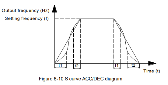
Diagram description (text version): Figure 6-10 S curve ACC/DEC: the output frequency rises from 0 to the setting frequency f along an S-shaped curve – the start part (t1, P6-08) and the end part (t2, P6-09) are rounded and the middle part is linear; deceleration to 0 follows the mirrored S curve with the same t1 and t2 portions. A straight line shows linear ACC/DEC for comparison.
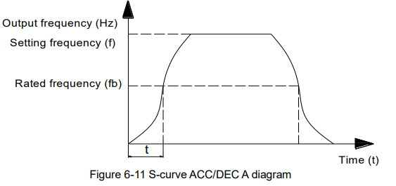
Diagram description (text version): Figure 6-11 S-curve ACC/DEC (as captioned in the source): the output frequency rises slowly at first, steeply around the rated frequency fb (time t to reach fb) and then flattens out before reaching the setting frequency f; deceleration follows the mirrored curve. Acceleration time above fb is given by the formula t = (4/9 × (f/fb)² + 5/9) × T.
| Parameter | Name | Factory default | Setting range |
|---|---|---|---|
| P6-10 | Stop mode | 0 | 0: Deceleration to stop 1: Coast to stop |
0: Deceleration to stop
After the stop command is valid, the inverter reduces the output frequency according to the DEC time and will stop after the frequency reduces to zero.
1: Coast to stop
After the stop command is valid, the inverter blocks the output immediately. The motor coasts to stop according to the mechanical inertia.
| Parameter | Name | Factory default | Setting range |
|---|---|---|---|
| P6-11 | DC braking start frequency after stop | 0.00Hz | 0.00Hz ~ P0-10 (maximum frequency) |
| P6-12 | DC braking waiting time after stop | 0.0s | 0.0s ~ 100.0s |
| P6-13 | DC braking current after stop | 0% | 0% ~ 100% |
| P6-14 | DC braking time after stop | 0.0s | 0.0s ~ 100.0s |
DC braking start frequency after stop: Start the DC braking when running frequency reaches this frequency determined by P6-11.
DC braking waiting time after stop: Inverter blocks the output before starting the DC braking. After this waiting time, the DC braking will be started so as to prevent over-current fault caused by DC braking at high speed.
DC brake current after stop: The value of P6-13 is the percentage of rated current of inverter. The bigger the DC braking current is, the greater the braking torque is.
DC brake time after stop: The time which is used to perform DC braking. If the time is 0, the DC braking will be invalid.
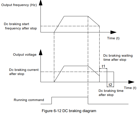
Diagram description (text version): Figure 6-12 DC braking: after the running command is removed, the output frequency decelerates; when it reaches the DC braking start frequency after stop (P6-11), the output stops, and after the DC braking waiting time t1 (P6-12) DC braking current (P6-13) is applied for the DC braking time t2 (P6-14).
| Parameter | Name | Factory default | Setting range |
|---|---|---|---|
| P6-15 | Braking usage ratio | 100% | 0% ~ 100% |
It is only valid for the inverter with built-in brake unit, can be used to adjust the braking effect of the brake unit.
Słowa kluczowe
Micno KE300, opis parametrów, parameter description, P5, P6, wyjścia przekaźnikowe, relay outputs, AO1, AO2, HDO, hamowanie DC, DC braking, krzywa S, S-curve, start mode