
6. Parameter Description – Part 5 (Groups P7–P8)
Streszczenie: Opis parametrów KE300 (część 5 z 8): panel i wyświetlanie (QUICK/JOG, parametry statusu) oraz funkcje rozszerzone (JOG, czasy ACC/DEC 2–4, częstotliwości skoku, FDT, detekcja prądu, timer, uśpienie i wybudzenie).
EN: KE300 parameter description (part 5 of 8): keypad and display (QUICK/JOG, status display) and enhanced functions (jog, ACC/DEC times 2–4, jump frequencies, FDT, current detection, timer, sleep and wake-up).
Dotyczy: falownik wektorowy Micno KE300 (zasilanie 1AC/3AC 220 V, 3AC 380 V, 3AC 660 V; moce 0,4–630 kW)
Źródło: dokumentacja producenta (Micno KE300 Series Inverter User Manual); tabele przepisane z obrazów na tekst, opisy rysunków – opracowanie Multiprojekt
Group P7 Keypad and Display
| Parameter | Name | Factory default | Setting range |
|---|---|---|---|
| P7-00 | Inverter rated power | Model dependent | 0.1kW ~ 1000.0kW |
Display inverter rated power.
| Parameter | Name | Factory default | Setting range |
|---|---|---|---|
| P7-01 | QUICK/JOG function selection | 0 | 0: Invalid 1: Switching between keypad command and remote command (terminal command and communication command) 2: FWD/REV switching 3: Forward Jog 4: Reverse Jog |
QUICK/JOG is a multifunctional key, whose function can be defined by the value
0: This key is invalid
1: Switching between keyboard command and remote operation. It refers to switching of command source, switching between the current command source and the keyboard control (local operation). If the current command source is keyboard control, this key is invalid.
2: Press QUICK/JOG, the running direction of inverter will change. It is only valid when keypad command is valid.
3: It can realize forward jog via QUICK/JOG key.
4: It can realize reverse jog via QUICK/JOG key.
| Parameter | Name | Factory default | Setting range |
|---|---|---|---|
| P7-02 | STOP/RST function selection | 1 | 0: Valid when keypad control 1: Always valid |
| Parameter | Name | Factory default | Setting range |
|---|---|---|---|
| P7-03 | Running status display 1 | 1F | 0000 ~ FFFF |
P7-03 – bit assignment
| Bit | Displayed value |
|---|---|
| 0 | Running frequency (Hz) |
| 1 | Setting frequency (Hz) |
| 2 | DC bus voltage (V) |
| 3 | Output voltage (V) |
| 4 | Output current (A) |
| 5 | Output power (kW) |
| 6 | Output torque |
| 7 | DI input status |
| 8 | DO output status |
| 9 | AI1 voltage (V) |
| 10 | AI2 voltage (V) |
| 11 | Radiator temperature |
| 12 | Count value |
| 13 | Length value |
| 14 | Load speed display |
| 15 | PID setting |
If the above parameters need to be displayed when running, set the corresponding positions to 1, change the binary number into a hexadecimal number and enter it into P7-03.
| Parameter | Name | Factory default | Setting range |
|---|---|---|---|
| P7-04 | Running status display 2 | 0 | 0000 ~ FFFF |
P7-04 – bit assignment
| Bit | Displayed value |
|---|---|
| 0 | PID feedback |
| 1 | PLC phase |
| 2 | HDI frequency (kHz) |
| 3 | Running frequency 2 (Hz) |
| 4 | Remain running time |
| 5 | AI1 voltage before calibration (V) |
| 6 | AI2 voltage before calibration (V) |
| 7 | Reserved |
| 8 | Linear speed |
| 9 | Current power-on time (Hour) |
| 10 | Current running time (Min) |
| 11 | HDO frequency (kHz) |
| 12 | Communication setting value |
| 13 | Reserved |
| 14 | Main frequency A display (Hz) |
| 15 | Auxiliary frequency B display (Hz) |
If the above parameters need to be displayed when running, set the corresponding positions to 1, change the binary number into a hexadecimal number and enter it into P7-04.
Operation display parameter is used to set the parameters which can be viewed when running.
There are at most 32 parameters can be viewed, set the status parameters via the binary bits of P7-03 and P7-04, and the display sequence starts from the lowest order of P7-03.
| Parameter | Name | Factory default | Setting range |
|---|---|---|---|
| P7-05 | Stop status display | 0 | 0000 ~ FFFF |
P7-05 – bit assignment
| Bit | Displayed value |
|---|---|
| 0 | Setting frequency (Hz) |
| 1 | Bus voltage (V) |
| 2 | DI input status |
| 3 | DO output status |
| 4 | AI1 voltage (V) |
| 5 | AI2 voltage (V) |
| 6 | Radiator temperature |
| 7 | Count value |
| 8 | Length value |
| 9 | PLC phase |
| 10 | Load speed |
| 11 | PID setting |
| 12 | HDI frequency |
| 13 | Reserved |
| 14 | Reserved |
| 15 | Reserved |
If the above parameters need to be displayed when stopped, set the corresponding positions to 1, change the binary number into a hexadecimal number and enter it into P7-05.
| Parameter | Name | Factory default | Setting range |
|---|---|---|---|
| P7-06 | Load speed display coefficient | 3.0000 | 0.0001 ~ 6.5000 |
The correspondence of the inverter output frequency and the load speed can be adjusted via this parameter when the load speed needs to be displayed.
| Parameter | Name | Factory default | Setting range |
|---|---|---|---|
| P7-07 | IGBT module temperature | – | 0.0 °C ~ 100.0 °C |
Display IGBT module temperature.
The over temperature protection values of different IGBT modules are not the same.
| Parameter | Name | Factory default | Setting range |
|---|---|---|---|
| P7-08 | Inverter rated voltage | Model dependent | 1V ~ 2000V |
Display inverter rated voltage
| Parameter | Name | Factory default | Setting range |
|---|---|---|---|
| P7-09 | Accumulated running time | – | 0h ~ 65535h |
Display the accumulated running time of the inverter. When the running time reaches the value set by P8-17, the digital output terminal outputs ON signal.
| Parameter | Name | Factory default | Setting range |
|---|---|---|---|
| P7-10 | Model No. | – | Inverter model No. |
| P7-11 | Software version No. | – | Control software version No. |
| P7-12 | Load speed display decimal place | 0 | 0: 0 decimal places 1: 1 decimal place 2: 2 decimal places 3: 3 decimal places |
The parameters are used to set load speed display decimal place. The following load speed calculation format for example:
If load speed display factor (P7-06) is 2.000, load speed decimal place (P7-12) is 2 (2 decimal places), when the running frequency is 40.00Hz, load speed is: 40.00×2.000=80.00 (2 decimal places displayed)
If the inverter stops, load speed is displayed as setting frequency corresponding speed, namely “setting load speed”. If setting frequency=50.00Hz, the stop status load speed is: 50.00×2.000=100.00 (2 decimal places displayed)
| Parameter | Name | Factory default | Setting range |
|---|---|---|---|
| P7-13 | Accumulated power-on time | 0h | 0h ~ 65535h |
Display the accumulated power-on time after production.
When this time reaches the value set by P8-17, the inverter multifunctional digital output function (24) outputs ON signal.
| Parameter | Name | Factory default | Setting range |
|---|---|---|---|
| P7-14 | Accumulated power consumption | – | 0kW ~ 65535kW |
Display the accumulated power consumption till now.
Group P8 Enhanced Function
| Parameter | Name | Factory default | Setting range |
|---|---|---|---|
| P8-00 | Jog running frequency | 2.00Hz | 0.00Hz ~ P0-10 (maximum frequency) |
| P8-01 | Jog acceleration time | 20.0s | 0.1s ~ 3600.0s |
| P8-02 | Jog deceleration time | 20.0s | 0.1s ~ 3600.0s |
It is used to define the reference frequency and ACC/DEC time of the inverter when jogging. During Jog running, the start mode is fixed to direct start (P6-00=0), the stop mode is fixed to deceleration to stop (P6-10=0).
| Parameter | Name | Factory default | Setting range |
|---|---|---|---|
| P8-03 | Acceleration time 2 | Model dependent | 0.1s ~ 3600.0s |
| P8-04 | Deceleration time 2 | Model dependent | 0.1s ~ 3600.0s |
| P8-05 | Acceleration time 3 | Model dependent | 0.1s ~ 3600.0s |
| P8-06 | Deceleration time 3 | Model dependent | 0.1s ~ 3600.0s |
| P8-07 | Acceleration time 4 | Model dependent | 0.1s ~ 3600.0s |
| P8-08 | Deceleration time 4 | Model dependent | 0.1s ~ 3600.0s |
KE300 series inverter supplies 4 kinds of ACC/DEC time. The principles of them are the same. Please refer to description of P0-17 and P0-18 for more details.
User can select the one of 4 kinds ACC/DEC time thought the different combination of DI terminals. See the description of P4-00~P4-05, then pay attention to Function (16) & Function (17) and Attached table 2.
| Parameter | Name | Factory default | Setting range |
|---|---|---|---|
| P8-09 | Jump frequency 1 | 0.00Hz | 0.00Hz ~ P0-10 (maximum frequency) |
| P8-10 | Jump frequency 2 | 0.00Hz | 0.00Hz ~ P0-10 (maximum frequency) |
| P8-11 | Jump frequency amplitude | 0.00Hz | 0.00 ~ P0-10 (maximum frequency) |
By means of setting jump frequency, the inverter can keep away from the mechanical resonance with the load. P8.09 and P8.10 are center value of frequency to be skipped.
If both P8-09 and P8-10 are 0, the jump frequency function is invalid no matter what P8.11 is.
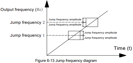
Diagram description (text version): Figure 6-13 Jump frequency: while the output frequency ramps up over time, it skips the bands around jump frequency 1 and jump frequency 2; each band extends by the jump frequency amplitude above and below the jump frequency, so the inverter does not run steadily inside these bands.
| Parameter | Name | Factory default | Setting range |
|---|---|---|---|
| P8-12 | FWD/REV dead time | 0.0s | 0.00s ~ 3600.0s |
FWD/REV dead time: The waiting and holding time before the motor changes its spinning direction after the inverter's output frequency is decreased to zero. It is the time taken by the motor to change its spinning direction when the inverter receives REV command during its running process. The time is shown in Figure 6-14:
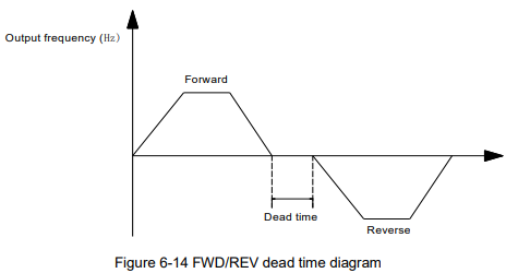
Diagram description (text version): Figure 6-14 FWD/REV dead time: the output frequency decelerates from forward running to 0 Hz, stays at 0 Hz for the dead time (P8-12) and then accelerates in the reverse direction.
FWD/REV dead time: The waiting and holding time before the motor changes its spinning direction after the inverter's output frequency is decreased to zero. It is the time taken by the motor to change its spinning direction when the inverter receives REV command during its running process. The time is shown in Figure 6-14:
| Parameter | Name | Factory default | Setting range |
|---|---|---|---|
| P8-13 | Reverse control | 0 | 0: Valid 1: Invalid |
It is used to set if the inverter can run reverse, P8-13 is set to 1 for the applications that the motor can not run reverse.
| Parameter | Name | Factory default | Setting range |
|---|---|---|---|
| P8-14 | Action when setting frequency lower than frequency lower limit | 0 | 0: Running at frequency lower limit 1: Stop 2: Zero speed running |
It is used to select the inverter running status when the setting frequency is lower than the frequency lower limit.
| Parameter | Name | Factory default | Setting range |
|---|---|---|---|
| P8-15 | Droop control | 0.00Hz | 0.00Hz ~ 10.00Hz |
When several motors drive the same load, each motor's load is different because of the difference of motor's rated speed. The load of different motors can be balanced through droop control function which makes the speed droop along with load increase.
When the motor outputs rated torque, actual frequency drop is equal to P8-15. User can adjust this parameter from small to big gradually during commissioning.
| Parameter | Name | Factory default | Setting range |
|---|---|---|---|
| P8-16 | Accumulated power-on arrival time | 0h | 0h ~ 36000h |
When the accumulated power on time (P7-13) reaches the value set by P8-16, the multifunctional digital DO outputs ON signal.
| Parameter | Name | Factory default | Setting range |
|---|---|---|---|
| P8-17 | Accumulated running arrival time | 0h | 0h ~ 36000h |
It is used to set the running time of the inverter.
When the accumulated running time (P7-09) reaches the value set by P8-17, the multifunctional digital DO outputs ON signal.
| Parameter | Name | Factory default | Setting range |
|---|---|---|---|
| P8-18 | Power-on running command valid protection selection | 0 | 0: No protection 1: Protection |
- If power-on running command is valid (for example, the terminal running command is close before power on), the inverter will not response the running command. After the running command is removed & valid again, the inverter will response.
- If the fault reset running command is valid, the inverter will not response the running commend, user must cancel the running command to remove the running protection status.
- This code is set to 1 so as to avoid dangerous caused by that motor responses running command during power-on or fault reset.
| Parameter | Name | Factory default | Setting range |
|---|---|---|---|
| P8-19 | Frequency detection value (FDT1) | 50.00Hz | 0.00Hz ~ P0-10 (maximum frequency) |
| P8-20 | Frequency detection lag (FDT1) | 5.0% | 0.0% ~ 100.0% (FDT1 level) |
When the output frequency reaches a certain preset frequency (FDT level), DO terminal will output an ON signal until output frequency drops below a certain frequency of FDT level (FDT level - FDT lag), as shown in following figure.
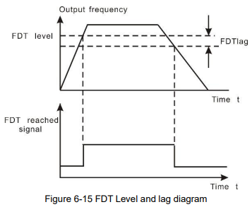
Diagram description (text version): Figure 6-15 FDT level and lag: the FDT reached signal turns ON when the output frequency rises above the FDT level and turns OFF only when the frequency falls below the FDT level minus the FDT lag (hysteresis).
| Parameter | Name | Factory default | Setting range |
|---|---|---|---|
| P8-21 | Frequency arrival detection amplitude | 0.0% | 0.00 ~ 100% (maximum frequency) |
When output frequency is within the detecting range of reference frequency, an ON-OFF signal will be output. The function can adjust the detecting range.
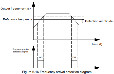
Diagram description (text version): Figure 6-16 Frequency arrival detection: the frequency arrival detection signal is ON while the output frequency is within the detection amplitude band (± P8-21) around the reference frequency – i.e. briefly while accelerating through the band, while running at the reference frequency, and while decelerating through the band.
| Parameter | Name | Factory default | Setting range |
|---|---|---|---|
| P8-22 | Jump frequency during ACC/DEC | 0 | 0: Invalid 1: Valid |
It is used to set if jump frequency is valid during ACC/DEC.
When valid, the running frequency is in the range of jump frequency, the actual running frequency will skip the boundary of the setting jump frequency.
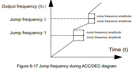
Diagram description (text version): Figure 6-17 Jump frequency during ACC/DEC: when P8-22 is valid, the output frequency ramps up and passes through the bands around jump frequency 1 and 2 (± jump frequency amplitude) by jumping vertically across them instead of ramping through.
| Parameter | Name | Factory default | Setting range |
|---|---|---|---|
| P8-25 | Acceleration time 1 and acceleration time 2 switching frequency point | 0.00Hz | 0.00Hz ~ P0-10 (maximum frequency) |
| P8-26 | Deceleration time 1 and deceleration time 2 switching frequency point | 0.00Hz | 0.00Hz ~ P0-10 (maximum frequency) |
This function is valid when don’t use DI terminal to switch ACC/DEC. Suitable for the inverter running process, choose different ACC/DEC time according to the running frequency range (instead of through DI terminals).
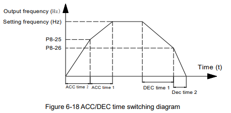
Diagram description (text version): Figure 6-18 ACC/DEC time switching: below the switching point P8-25 the inverter accelerates with acceleration time 2, above it with acceleration time 1 up to the setting frequency; when decelerating it uses deceleration time 1 down to P8-26 and deceleration time 2 below P8-26.
During ACC, if the running frequency is lower than P8-25, then select ACC time 2, if the running frequency is higher than P8-25, then select ACC time 1.
During DEC, if the running frequency is higher than P8-26, then select DEC time 1, if the running frequency is lower than P8-26, then select DEC time 2.
| Parameter | Name | Factory default | Setting range |
|---|---|---|---|
| P8-27 | Terminal jog priority | 0 | 0: Invalid 1: Valid |
It is used to set whether the priority of terminal jog function is the highest.
When terminal jog priority is valid, if terminal jog command appears when running, the inverter switches to terminal jog running status.
| Parameter | Name | Factory default | Setting range |
|---|---|---|---|
| P8-28 | Frequency detection value (FDT2) | 50.00Hz | 0.00Hz ~ P0-10 (maximum frequency) |
| P8-29 | Frequency detection lag value (FDT2) | 5.0% | 0.0% ~ 100.0% (FDT2 level) |
This frequency detection function is the same as FDT1’s, please refer to description of FDT1 (P8-19, P8-20).
| Parameter | Name | Factory default | Setting range |
|---|---|---|---|
| P8-30 | Any arrival frequency detection value 1 | 50.00Hz | 0.00Hz ~ P0-10 (maximum frequency) |
| P8-31 | Any arrival frequency detection amplitude 1 | 0.0% | 0.0% ~ 100.0% (maximum frequency) |
| P8-32 | Any arrival frequency detection value 2 | 50.00Hz | 0.00Hz ~ P0-10 (maximum frequency) |
| P8-33 | Any arrival frequency detection amplitude 2 | 0.0% | 0.0% ~ 100.0% (maximum frequency) |
When the output frequency reaches positive or negative detection amplitude of frequency detection value, DO outputs ON signal. KE300 series inverter provides two parameters of any arrival frequency detection value, used to set frequency value and frequency detection range.
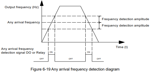
Diagram description (text version): Figure 6-19 Any arrival frequency detection: the DO or relay output is ON while the output frequency is within the band of the selected arrival frequency ± frequency detection amplitude – once while accelerating through the band and once while decelerating through it.
| Parameter | Name | Factory default | Setting range |
|---|---|---|---|
| P8-34 | Zero-current detection level | 5.0% | 0.0% ~ 300.0% (100.0% corresponds to motor rated current) |
| P8-35 | Zero-current detection delay time | 0.10s | 0.00s ~ 360.00s |
When the output current ≤ zero current detection level, lasts for longer than zero current detection delay time, DO terminal outputs ON signal.
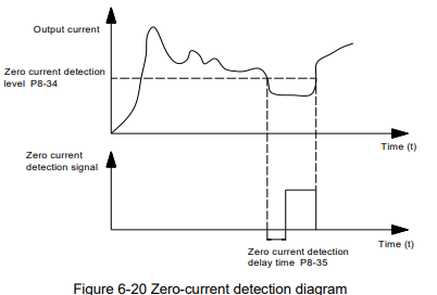
Diagram description (text version): Figure 6-20 Zero-current detection: when the output current drops below the zero current detection level P8-34 and stays below it for the delay time P8-35, the zero current detection signal turns ON; it turns OFF when the current rises above the level again.
| Parameter | Name | Factory default | Setting range |
|---|---|---|---|
| P8-36 | Output current over limit value | 200.0% | 0.0% (no detection) 0.1% ~ 300.0% (motor rated current) |
| P8-37 | Output current over limit detection delay time | 0.00s | 0.00s ~ 360.00s |
When the output current is bigger than or over-limit detection point, lasts for longer than software over current point detection delay time, DO terminal outputs ON signal.
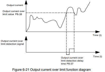
Diagram description (text version): Figure 6-21 Output current over limit: when the output current exceeds the over limit value P8-36 for longer than the detection delay time P8-37, the output current over limit detection signal turns ON.
| Parameter | Name | Factory default | Setting range |
|---|---|---|---|
| P8-38 | Any arrival current 1 | 100.0% | 0.0% ~ 300.0% (motor rated current) |
| P8-39 | Any arrival current 1 amplitude | 0.0% | 0.0% ~ 300.0% (motor rated current) |
| Parameter | Name | Factory default | Setting range |
|---|---|---|---|
| P8-40 | Any arrival current 2 | 100.0% | 0.0% ~ 300.0% (motor rated current) |
| P8-41 | Any arrival current 2 amplitude | 0.0% | 0.0% ~ 300.0% (motor rated current) |
When the output current is in the range of positive or negative detection amplitude of setting any arrival current, DO terminal outputs ON signal. KE300 series inverter provides two parameters of any arrival current and detection amplitude.
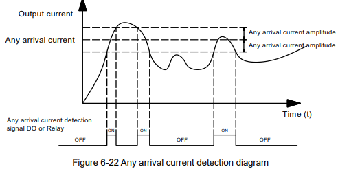
Diagram description (text version): Figure 6-22 Any arrival current detection: the DO or relay output is ON whenever the output current is within the band of the any arrival current ± amplitude, and OFF when the current is outside this band.
| Parameter | Name | Factory default | Setting range |
|---|---|---|---|
| P8-42 | Timing function selection | 0 | 0: Invalid 1: Valid |
| P8-43 | Timing running time selection | 0 | 0: P8-44 1: AI1 2: AI2 3: Keypad potentiometer Analog input scale 100% corresponds to P8-44 (the source says F8-44) |
| P8-44 | Timing running time | 0.0Min | 0.0Min ~ 3600.0Min |
The parameters are used to set the inverter timing running function.
When P8-42 timing function selection is valid, timing starts after the inverter starts, reaches the setting timing running time, the inverter stops automatically, meantime, DO terminal outputs ON signal.
Timing starts from 0 when the inverter starts, timing remain running time can be viewed via U0-20.
The timing running time is set by P8-43, P8-44, time unit is minute.
| Parameter | Name | Factory default | Setting range |
|---|---|---|---|
| P8-45 | AI1 input voltage protection lower limit | 3.10V | 0.00V ~ P8-46 |
| P8-46 | AI1 input voltage protection upper limit | 6.80V | P8-45 ~ 10.00V |
When the analog input AI1 value is bigger than P8-46, or smaller than P8-45, DO terminal outputs “AI1 input over limit” ON signal, used to indicate whether AI1 input voltage is in the setting range.
| Parameter | Name | Factory default | Setting range |
|---|---|---|---|
| P8-47 | Module temperature arrival | 75 °C | 0 °C ~ 100 °C |
When the converter radiator temperature reaches this value, DO outputs “module temperature arrival” ON signal.
| Parameter | Name | Factory default | Setting range |
|---|---|---|---|
| P8-48 | Cooling fan control | 0 | 0: Fan runs when operating 1: Fan always runs |
It is used to select cooling fan action mode,
When the selection is 0, cooling fans run when the inverter running, when the inverter stops & the radiator temperature is higher than 40℃, cooling fans run.
When the inverter stops & the radiator temperature is lower than 40℃, cooling fans stop.
When the selection is 1, cooling fans always run after power-on.
| Parameter | Name | Factory default | Setting range |
|---|---|---|---|
| P8-49 | Wake up frequency | 3.0 | 0.00 ~ PA-04 (PID given feedback range) |
| P8-50 | Wake-up delay time | 0.0s | 0.0s ~ 3600.0s |
| P8-51 | Dormancy frequency | 0.00Hz | 0.00Hz ~ P0-10 (maximum frequency) |
| P8-52 | Dormancy delay time | 0.0s | 0.0s ~ 3600.0s |
The parameters are used to achieve dormancy and wake up function in water-supply applications.
During running, when the setting frequency ≤ P8-51 dormancy frequency, lasts for P8-52 delay time, the inverter enters into dormancy status & stops automatically.
When the inverter is in the dormancy status & the present running command is valid, if the setting frequency ≥ P8-49 wake up frequency lasts for P8-50 delay time, the inverter starts.
Normally please set wake up frequency ≥ dormancy frequency. Setting both wake up frequency and dormancy frequency are 0.00Hz, then wake up and dormancy functions are invalid.
When starting dormancy function, if frequency source is set by PID, PA-28 will affect whether dormancy status PID calculates or not, PID stop calculation function must be set to be 1 (namely PA-28=1).
| Parameter | Name | Factory default | Setting range |
|---|---|---|---|
| P8-53 | Running arrival time setting | 0.0Min | 0.0Min ~ 3600.0Min |
When the running time reaches the time set by P8-53, DO outputs “Running arrival time setting” ON signal.
Słowa kluczowe
Micno KE300, opis parametrów, parameter description, P7, P8, QUICK/JOG, wyświetlanie, display, JOG, FDT, częstotliwość skoku, jump frequency, uśpienie, dormancy, wake up