
6. Parameter Description – Part 8 (Group U0)
Streszczenie: Opis parametrów KE300 (część 8 z 8): parametry monitorowania U0 (częstotliwości, napięcia, prądy, stany wejść i wyjść, liczniki).
EN: KE300 parameter description (part 8 of 8): U0 monitoring parameters (frequencies, voltages, currents, I/O states, counters).
Dotyczy: falownik wektorowy Micno KE300 (zasilanie 1AC/3AC 220 V, 3AC 380 V, 3AC 660 V; moce 0,4–630 kW)
Źródło: dokumentacja producenta (Micno KE300 Series Inverter User Manual); tabele przepisane z obrazów na tekst, opisy rysunków – opracowanie Multiprojekt
Nawigacja: część 8 z 8 · ← poprzednia część (Part 7 (Groups PB–A0))
Group U0 Monitoring Parameters
For the convenience of the field debugging, U0 group indicates running status of inverter. User can view them on the keypad.
| Code | Name | Range |
|---|---|---|
| U0-00 | Running frequency | 0.00 ~ 320.00Hz (P0-22=2); 0.0 ~ 3200.0Hz (P0-22=1) |
| U0-01 | Setting frequency | 0.00 ~ 320.00Hz (P0-22=2); 0.0 ~ 3200.0Hz (P0-22=1) |
U0-00 displays absolute value of theoretical running frequency of the inverter.
U0-01 displays absolute value of setting frequency of the inverter.
The actual output frequency of inverter refers to U0-19.
| Code | Name | Range |
|---|---|---|
| U0-02 | DC bus voltage | 0.0V ~ 3000.0V |
U0-02 displays the voltage of DC bus.
| Code | Name | Range |
|---|---|---|
| U0-03 | Output voltage | 0V ~ 1140V |
U0-03 displays the output voltage of inverter at run time.
| Code | Name | Range |
|---|---|---|
| U0-04 | Output current | 0.00A ~ 655.35A (rated power ≤ 55kW); 0.0A ~ 6553.5A (rated power > 55kW) |
U0-04 displays the output current of inverter at run time.
| Code | Name | Range |
|---|---|---|
| U0-05 | Output power | 0 ~ 32767 |
U0-05 displays the output power of inverter at run time.
| Code | Name | Range |
|---|---|---|
| U0-06 | Output torque | -200.0% ~ 200.0% |
U0-06 displays the output torque of inverter at run time
| Code | Name | Range |
|---|---|---|
| U0-07 | DI input status | 0 ~ 32767 |
U0-07 displays the digital value Input terminal state which can be expressed by a 8-bit binary code; if the inverter detects that the input of corresponding terminal is high level(closed), then this bit is set to "1", if the input of corresponding terminal is low level(open), then the bit is set to "0". The relationship between Digital value Input terminal and binary code is shown below.
U0-07 – DI input status bits
| Bit | Signal |
|---|---|
| Bit0 | DI1 |
| Bit1 | DI2 |
| Bit2 | DI3 |
| Bit3 | DI4 |
| Bit4 | DI5 |
| Bit5 | DI6 |
| Bit6 | DI7 |
| Bit7 | – |
| Code | Name | Range |
|---|---|---|
| U0-08 | DO output status | 0 ~ 1023 |
U0-07 displays the digital value output terminal state which can be expressed by a 8-bit binary code; if the inverter detects that the output of corresponding terminal is high level (closed), then this bit is set to "1", if the output of corresponding terminal is low level (open), then the bit is set to "0". The relationship between Digital value output terminal and binary code is shown below.
U0-08 – DO output status bits
| Bit | Signal |
|---|---|
| Bit0 | DO3 |
| Bit1 | Relay 1 |
| Bit2 | Relay 2 |
| Bit3 | DO1 |
| Bit4 | DO2 |
| Bit5 | – |
| Bit6 | – |
| Bit7 | – |
| Code | Name | Range |
|---|---|---|
| U0-09 | AI1 voltage | -10 ~ 10V |
U0-09 displays the input voltage of AI1.
| Code | Name | Range |
|---|---|---|
| U0-10 | AI2 voltage | -10 ~ 10V |
U0-10 displays the input voltage of AI2.
| Code | Name | Range |
|---|---|---|
| U0-11 | Radiator temperature | -20 ~ 100 °C |
U0-11 displays the current temperature of radiator.
| Code | Name | Range |
|---|---|---|
| U0-12 | Count value | – |
U0-12 displays the current value of counter.
| Code | Name | Range |
|---|---|---|
| U0-13 | Length value | – |
U0-13 displays the current value of length.
| Code | Name | Range |
|---|---|---|
| U0-14 | Load speed | 0 ~ 65535 |
U0-14 displays the speed of load. Refer to the description of P7-12 in user manual.
| Code | Name | Range |
|---|---|---|
| U0-15 | PID setting | 0 ~ 65535 |
| U0-16 | PID feedback | 0 ~ 65535 |
U0-15 displays the setting value of PID.
U0-16 displays the feedback value of PID.
Take the following formulas as follows:
The setting value of PID= the setting (percentage) of PID × PA-04
The feedback value of PID=the feedback (percentage) of PID × PA-04
| Code | Name | Range |
|---|---|---|
| U0-17 | PLC phase | 0 ~ F |
U0-14 displays the current step when inverter is running in simple PLC mode.
The relationship between displayed value and current step is shown below.
U0-17 – PLC phase display
| Displayed value | Inverter is running at step X |
|---|---|
| 1 | X: 0 |
| 2 | X: 1 |
| …… | …… |
| F | X: 15 |
| Code | Name | Range |
|---|---|---|
| U0-18 | HDI input pulse frequency | 0.00 ~ 100.0kHz |
U0-18 displays the sampling frequency of High-speed-pulse input (HDI). The smallest unit is 0.01 KHz.
| Code | Name | Range |
|---|---|---|
| U0-19 | Feedback speed | -320.00 ~ 320.00Hz; -3200.0 ~ 3200.0Hz |
U0-19 displays the actual output frequency of inverter:
When P0-22 is set to 1, the range is -3200.0 to 3200.0. (Unit: Hz)
When P0-22 is set to 2, the range is -320.00 to 320.00. (Unit: Hz)
| Code | Name | Range |
|---|---|---|
| U0-20 | Remain running time | 0.0 ~ 6500.0min |
U0-20 displays remain running time when inverter is running at timing running mode. (Refer to P8-42, P8-43 and P8-44).
| Code | Name | Range |
|---|---|---|
| U0-21 | AI1 voltage before calibration | 0.00 ~ 10.57V |
| U0-22 | AI2 voltage before calibration | 0.00 ~ 10.57V |
| U0-23 | Keypad potentiometer voltage before calibration | 0.00 ~ 10.57V |
U0-21 displays the sampling voltage of analog input 1(AI1).
U0-22 displays the sampling voltage of analog input 2(AI2).
The actual input voltage is corrected value after linear calibration, so as to reduce the deviation between sampling voltage and the actual input voltage.
U0-09 and U0-10 display the actual voltages.
| Code | Name | Range |
|---|---|---|
| U0-24 | Linear velocity | 0 ~ 65535 m/min |
U0-24 displays the sampling linear velocity of High-speed-pulse input (HDI). The unit is meter per minute (m/min).
It can be calculated according to number of the actual sampling pulse and PB-07(number of pulse per meter).
| Code | Name | Range |
|---|---|---|
| U0-27 | HDI input pulse frequency | 0 ~ 65535Hz |
U0-27 displays the sampling frequency of High-speed-pulse input (HDI). The unit is 1 Hz. Actually, U0-27 displays the same data with U0-18. The only difference is the unit.
| Code | Name | Range |
|---|---|---|
| U0-28 | Communication setting value | -100 ~ 100% |
U0-28 displays the data written to address 0X1000.
| Code | Name | Range |
|---|---|---|
| U0-29 | Reserved | – |
| Code | Name | Range |
|---|---|---|
| U0-30 | Main frequency A display | 0.00 ~ 320.00Hz |
U0-30 displays the frequency of main reference-input-channel (Refer to P0-03).
When P0-22 is set to 1, the range is -3200.0 to 3200.0 (Unit: Hz).
When P0-22 is set to 2, the range is -320.00 to 320.00 (Unit: Hz).
| Code | Name | Range |
|---|---|---|
| U0-31 | Auxiliary frequency B display | 0.00 ~ 320.00Hz |
U0-31 displays the frequency of auxiliary reference-input-channel (Refer to P0-04).
When P0-22 is set to 1, the range is -3200.0 to 3200.0 (Unit: Hz).
When P0-22 is set to 2, the range is -320.00 to 320.00 (Unit: Hz).
| Code | Name | Range |
|---|---|---|
| U0-32 | Reserved | – |
| U0-33 | Reserved | – |
| Code | Name | Range |
|---|---|---|
| U0-34 | Motor temperature | 0 ~ 200 °C |
U0-43 displays the current temperature of motor.
NOTE: This code is reserved (not available in present).
| Code | Name | Range |
|---|---|---|
| U0-35 | Target torque | -200 ~ 200% |
U0-43 displays the current upper limit setting of torque. Refer to P2-09 and P2-10
| Code | Name | Range |
|---|---|---|
| U0-36 | Reserved | – |
| Code | Name | Range |
|---|---|---|
| U0-37 | Power factor angle | – |
U0-43 displays the current power factor angle.
| Code | Name | Range |
|---|---|---|
| U0-38 | Reserved | – |
| U0-39 | Reserved | – |
| U0-40 | Reserved | – |
| Code | Name | Range |
|---|---|---|
| U0-41 | Input status visual display | – |
U0-41 displays the input terminal state on the keypad intuitively.
Take the description for reference:
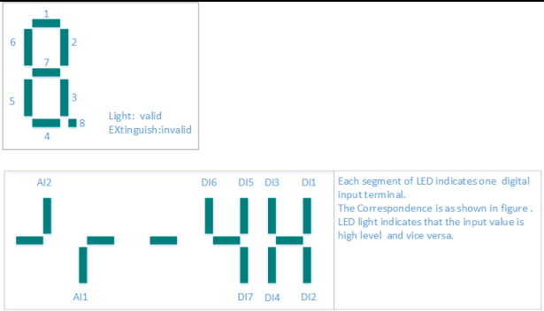
Diagram description (text version): U0-41 input status visual display: each segment of the 7-segment LED display (segments 1–8 of a digit; lit = valid, off = invalid) shows one digital input. In the example display the segments are assigned to AI2, AI1, DI6, DI5, DI3, DI1 (upper segments) and DI7, DI4, DI2 (lower segments); a lit segment means the input is at high level, and vice versa.
| Code | Name | Range |
|---|---|---|
| U0-42 | DO input status visual display | – |
U0-42 displays the digital value output terminal state on the keypad intuitively
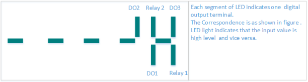
Diagram description (text version): U0-42 output status visual display: each LED segment indicates one digital output – DO2, Relay 2 and DO3 (upper segments) and DO1 and Relay 1 (lower segments); a lit segment means the output is at high level, and vice versa.
| Code | Name | Range |
|---|---|---|
| U0-43 | DO input status visual display 1 | – |
U0-43 displays whether intuitive display function 1-40 are valid or not.
There are 5 digital tubes on keypad. Every digital tube has 8 segments, and each segment indicates a certain function selection.
Define digital tube as shown in figure.
Digital tubes from left to right represent intuitive display function 1-8, 9-16, 7-24, 25-32, 33-40.
| Code | Name | Range |
|---|---|---|
| U0-44 | DI input status visual display 2 | – |
U0-44 displays whether intuitive display function 41-59 are valid or not.
There are 5 digital tubes on keypad. Every digital tube has 8 segments, and each segment indicates a certain function selection. Digital tubes from left to right represent intuitive display function 41-48, 49 56, 57-59.
NOTE: U0-33 and U0-34 are testing codes for manufacturers
| Code | Name | Range |
|---|---|---|
| U0-45 … U0-58 | Reserved | – |
| Code | Name | Range |
|---|---|---|
| U0-59 | Setting frequency | -100% ~ 100% |
| U0-60 | Running frequency | -100% ~ 100% |
U0-59 displays current setting frequency.
U0-60 displays current running frequency.
100% is corresponding to Max. frequency (P0-10).
| Code | Name | Range |
|---|---|---|
| U0-61 | Inverter status | 0 ~ 65535 |
U0-61 displays information of inverter running status. Take the following as reference.
NOTE: A digital tube is corresponding to one bit above.
U0-61 – inverter status bits
| Bits | Meaning |
|---|---|
| Bit 0 & bit 1 | 0: stop; 1: forward; 2: reverse |
| Bit 2 & bit 3 | 0: constant speed; 1: acceleration; 2: deceleration |
| Bit 4 | 0: the voltage of DC bus is normal; 1: under voltage |
Słowa kluczowe
Micno KE300, opis parametrów, parameter description, U0, monitorowanie, monitoring, U0-61, status falownika, inverter status, wizualizacja DI/DO