8. Troubleshooting
Streszczenie: Usuwanie usterek KE300: kody błędów E-01…E-40 z przyczynami i rozwiązaniami oraz typowe problemy i sposoby ich usunięcia.
EN: KE300 troubleshooting: fault codes E-01…E-40 with causes and solutions, plus common faults and remedies.
Dotyczy: falownik wektorowy Micno KE300 (zasilanie 1AC/3AC 220 V, 3AC 380 V, 3AC 660 V; moce 0,4–630 kW)
Źródło: dokumentacja producenta (Micno KE300 Series Inverter User Manual); tabele przepisane z obrazów na tekst – opracowanie Multiprojekt
8.1 Fault and Trouble Shooting
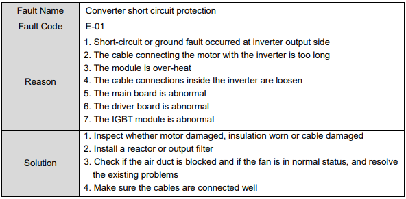
E-01
| Item | Description |
|---|---|
| Fault
| Converter
|
| Fault
| E-01 |
| Reason | 1.
2.
inverter istoo long |
| Solution | 1. Inspect whether motor damaged, insulation worn or cable damaged 2. Install a reactor or output filter 3. Check if the air duct is blocked and if the fan is in normal status, and resolve the existing problems 4. Make sure the cables are connected well |










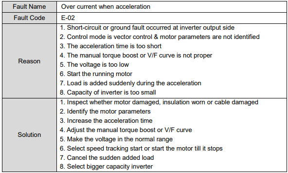
E-02 – Over Current when Acceleration
| Item | Description |
|---|---|
| Fault name | Over current when acceleration |
| Fault code | E-02 |
| Reason | 1. Short-circuit or ground fault occurred at inverter output side 2. Control mode is vector control and motor parameters are not identified 3. The acceleration time is too short 4. The manual torque boost or V/F curve is not proper 5. The voltage is too low 6. Start the running motor 7. Load is added suddenly during the acceleration 8. Capacity of inverter is too small |
| Solution | 1. Inspect whether motor damaged, insulation worn or cable damaged 2. Identify the motor parameters 3. Increase the acceleration time 4. Adjust the manual torque boost or V/F curve 5. Make the voltage in the normal range 6. Select speed tracking start or start the motor till it stops 7. Cancel the sudden added load 8. Select bigger capacity inverter |
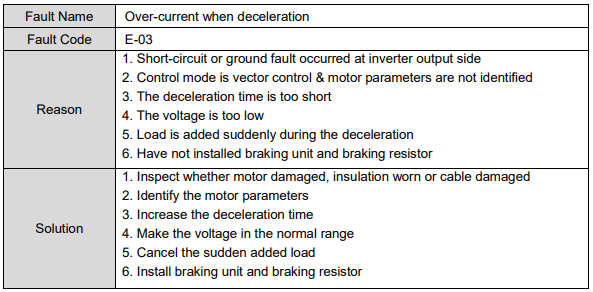
E-03 – Over-current when Deceleration
| Item | Description |
|---|---|
| Fault name | Over-current when deceleration |
| Fault code | E-03 |
| Reason | 1. Short-circuit or ground fault occurred at inverter output side 2. Control mode is vector control and motor parameters are not identified 3. The deceleration time is too short 4. The voltage is too low 5. Load is added suddenly during the deceleration 6. Have not installed braking unit and braking resistor |
| Solution | 1. Inspect whether motor damaged, insulation worn or cable damaged 2. Identify the motor parameters 3. Increase the deceleration time 4. Make the voltage in the normal range 5. Cancel the sudden added load 6. Install braking unit and braking resistor |
E-04 – Over-current when Constant Speed Running
| Item | Description |
|---|---|
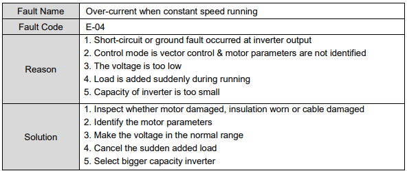
| Fault name | Over-current when constant speed running |
| Fault code | E-04 |
| Reason | 1. Short-circuit or ground fault occurred at inverter output 2. Control mode is vector control and motor parameters are not identified 3. The voltage is too low 4. Load is added suddenly during running 5. Capacity of inverter is too small |
| Solution | 1. Inspect whether motor damaged, insulation worn or cable damaged 2. Identify the motor parameters 3. Make the voltage in the normal range 4. Cancel the sudden added load 5. Select bigger capacity inverter |
E-05 – Over-voltage when Acceleration
| Item | Description |
|---|---|
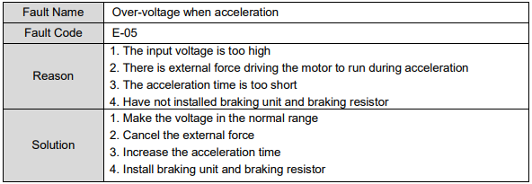
| Fault name | Over-voltage when acceleration |
| Fault code | E-05 |
| Reason | 1. The input voltage is too high 2. There is external force driving the motor to run during acceleration 3. The acceleration time is too short 4. Have not installed braking unit and braking resistor |
| Solution | 1. Make the voltage in the normal range 2. Cancel the external force 3. Increase the acceleration time 4. Install braking unit and braking resistor |
E-06 – Over-voltage when Deceleration
| Item | Description |
|---|---|
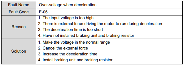
| Fault name | Over-voltage when deceleration |
| Fault code | E-06 |
| Reason | 1. The input voltage is too high 2. There is external force driving the motor to run during deceleration 3. The deceleration time is too short 4. Have not installed braking unit and braking resistor |
| Solution | 1. Make the voltage in the normal range 2. Cancel the external force 3. Increase the deceleration time 4. Install braking unit and braking resistor |
E-07 – Over-voltage when Constant Speed Running
| Item | Description |
|---|---|
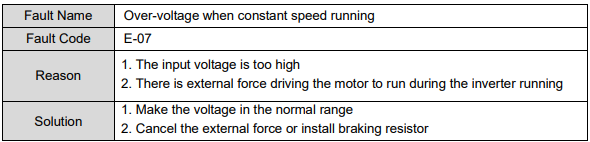
| Fault name | Over-voltage when constant speed running |
| Fault code | E-07 |
| Reason | 1. The input voltage is too high 2. There is external force driving the motor to run during the inverter running |
| Solution | 1. Make the voltage in the normal range 2. Cancel the external force or install braking resistor |
E-08 – Power-supply Fault
| Item | Description |
|---|---|
| Fault name | Power-supply fault |
| Fault code | E-08 |
| Reason | The input voltage is out of range |
| Solution | Make the voltage in the normal range |
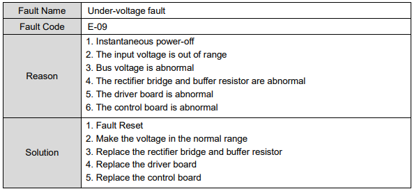
E-09 – Under-voltage Fault
| Item | Description |
|---|---|
| Fault name | Under-voltage fault |
| Fault code | E-09 |
| Reason | 1. Instantaneous power-off 2. The input voltage is out of range 3. Bus voltage is abnormal 4. The rectifier bridge and buffer resistor are abnormal 5. The driver board is abnormal 6. The control board is abnormal |
| Solution | 1. Fault reset 2. Make the voltage in the normal range 3. Replace the rectifier bridge and buffer resistor 4. Replace the driver board 5. Replace the control board |
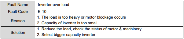
E-10 – Inverter Over Load
| Item | Description |
|---|---|
| Fault name | Inverter over load |
| Fault code | E-10 |
| Reason | 1. The load is too heavy or motor blockage occurs 2. Capacity of inverter is too small |
| Solution | 1. Reduce the load, check the status of motor and machinery 2. Select bigger capacity inverter |
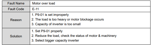
E-11 – Motor Over Load
| Item | Description |
|---|---|
| Fault name | Motor over load |
| Fault code | E-11 |
| Reason | 1. P9-01 is set improperly 2. The load is too heavy or motor blockage occurs 3. Capacity of inverter is too small |
| Solution | 1. Set P9-01 properly 2. Reduce the load, check the status of motor and machinery 3. Select bigger capacity inverter |
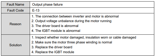
E-13 – Output Phase Failure
| Item | Description |
|---|---|
| Fault name | Output phase failure |
| Fault code | E-13 |
| Reason | 1. The connection between inverter and motor is abnormal 2. Output voltage unbalance during the motor running 3. The driver board is abnormal 4. The IGBT module is abnormal |
| Solution | 1. Inspect whether motor damaged, insulation worn or cable damaged 2. Make sure the motor three phase winding is normal 3. Replace the driver board 4. Replace the IGBT module |
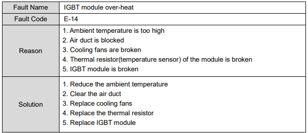
E-14 – IGBT Module Over-heat
| Item | Description |
|---|---|
| Fault name | IGBT module over-heat |
| Fault code | E-14 |
| Reason | 1. Ambient temperature is too high 2. Air duct is blocked 3. Cooling fans are broken 4. Thermal resistor (temperature sensor) of the module is broken 5. IGBT module is broken |
| Solution | 1. Reduce the ambient temperature 2. Clear the air duct 3. Replace cooling fans 4. Replace the thermal resistor 5. Replace IGBT module |
E-15 – Peripheral Device Fault
| Item | Description |
|---|---|
| Fault name | Peripheral device fault |
| Fault code | E-15 |
| Reason | DI terminal receives an external fault signal generated by peripheral device |
| Solution | Reset running |
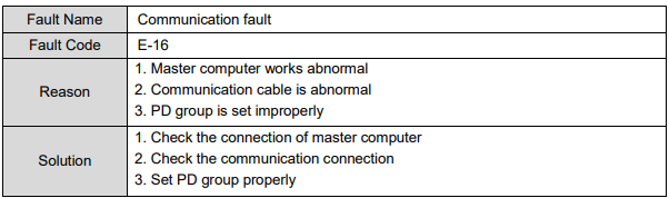
E-16 – Communication Fault
| Item | Description |
|---|---|
| Fault name | Communication fault |
| Fault code | E-16 |
| Reason | 1. Master computer works abnormal 2. Communication cable is abnormal 3. PD group is set improperly |
| Solution | 1. Check the connection of master computer 2. Check the communication connection 3. Set PD group properly |
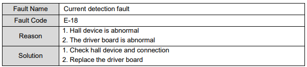
E-18 – Current Detection Fault
| Item | Description |
|---|---|
| Fault name | Current detection fault |
| Fault code | E-18 |
| Reason | 1. Hall device is abnormal 2. The driver board is abnormal |
| Solution | 1. Check hall device and connection 2. Replace the driver board |
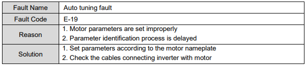
E-19 – Auto Tuning Fault
| Item | Description |
|---|---|
| Fault name | Auto tuning fault |
| Fault code | E-19 |
| Reason | 1. Motor parameters are set improperly 2. Parameter identification process is delayed |
| Solution | 1. Set parameters according to the motor nameplate 2. Check the cables connecting inverter with motor |
E-21 – EEPROM Read/write Fault
| Item | Description |
|---|---|
| Fault name | EEPROM read/write fault |
| Fault code | E-21 |
| Reason | EEPROM chip is broken |
| Solution | Replace the main board |
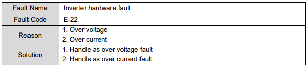
E-22 – Inverter Hardware Fault
| Item | Description |
|---|---|
| Fault name | Inverter hardware fault |
| Fault code | E-22 |
| Reason | 1. Over voltage 2. Over current |
| Solution | 1. Handle as over voltage fault 2. Handle as over current fault |
E-23 – Short-circuit to Ground Fault
| Item | Description |
|---|---|
| Fault name | Short-circuit to ground fault |
| Fault code | E-23 |
| Reason | The motor is short-circuit to ground |
| Solution | Replace cables or motor |
E-26 – Accumulated Running Time Arrival Fault
| Item | Description |
|---|---|
| Fault name | Accumulated running time arrival fault |
| Fault code | E-26 |
| Reason | The accumulated running time reaches the setting value |
| Solution | Clear the record information via parameter initialization function |
E-27 – Customized Fault 1
| Item | Description |
|---|---|
| Fault name | Customized fault 1 |
| Fault code | E-27 |
| Reason | DI terminal receives signal of customized fault 1 |
| Solution | Reset running |
E-28 – Customized Fault 2
| Item | Description |
|---|---|
| Fault name | Customized fault 2 |
| Fault code | E-28 |
| Reason | DI terminal receives signal of customized fault 2 |
| Solution | Reset running |
E-29 – Accumulated Power-on Time Arrival Fault
| Item | Description |
|---|---|
| Fault name | Accumulated power-on time arrival fault |
| Fault code | E-29 |
| Reason | The accumulated power-on time reaches the setting value |
| Solution | Clear the record information via parameter initialization function |
E-30 – Off-load Fault
| Item | Description |
|---|---|
| Fault name | Off-load fault |
| Fault code | E-30 |
| Reason | The inverter running current is smaller than P9-64 |
| Solution | Confirm if the load breaks away and P9-64 and P6-65 (probably P9-65) are set properly |
E-31 – PID Feedback Lost Fault when Running
| Item | Description |
|---|---|
| Fault name | PID feedback lost fault when running |
| Fault code | E-31 |
| Reason | PID feedback is smaller than PA-26 |
| Solution | Check PID feedback signal or set PA-26 properly |
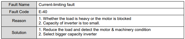
E-40 – Current-limiting Fault
| Item | Description |
|---|---|
| Fault name | Current-limiting fault |
| Fault code | E-40 |
| Reason | 1. Whether the load is heavy or the motor is blocked 2. Capacity of inverter is too small |
| Solution | 1. Reduce the load and detect the motor and machinery condition 2. Select bigger capacity inverter |
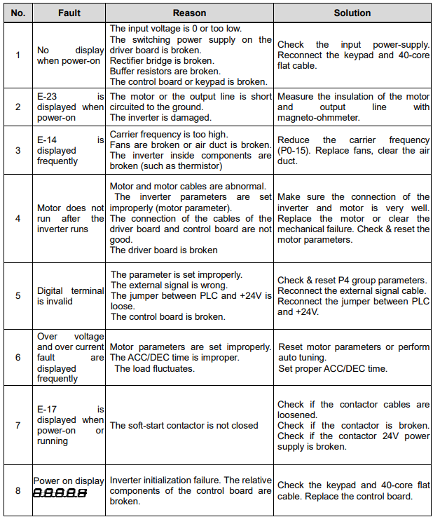
8.2 Common Faults and Solutions
| No. | Fault | Reason | Solution |
|---|---|---|---|
| 1 | No display when power-on | The input voltage is 0 or too low. The switching power supply on the driver board is broken. Rectifier bridge is broken. Buffer resistors are broken. The control board or keypad is broken. | Check the input power supply. Reconnect the keypad and 40-core flat cable. |
| 2 | E-23 is displayed when power-on | The motor or the output line is short-circuited to the ground. The inverter is damaged. | Measure the insulation of the motor and output line with a megohmmeter (magneto-ohmmeter). |
| 3 | E-14 is displayed frequently | Carrier frequency is too high. Fans are broken or air duct is blocked. The inverter inside components are broken (such as thermistor). | Reduce the carrier frequency (P0-15). Replace fans, clear the air duct. |
| 4 | Motor does not run after the inverter runs | Motor and motor cables are abnormal. The inverter parameters are set improperly (motor parameter). The connection of the cables of the driver board and control board are not good. The driver board is broken. | Make sure the connection of the inverter and motor is very well. Replace the motor or clear the mechanical failure. Check and reset the motor parameters. |
| 5 | Digital terminal is invalid | The parameter is set improperly. The external signal is wrong. The jumper between PLC and +24V is loose. The control board is broken. | Check and reset P4 group parameters. Reconnect the external signal cable. Reconnect the jumper between PLC and +24V. |
| 6 | Over voltage and over current fault are displayed frequently | Motor parameters are set improperly. The ACC/DEC time is improper. The load fluctuates. | Reset motor parameters or perform auto tuning. Set proper ACC/DEC time. |
| 7 | E-17 is displayed when power-on or running | The soft-start contactor is not closed. | Check if the contactor cables are loosened. Check if the contactor is broken. Check if the contactor 24V power supply is broken. |
| 8 | Power on display 8.8.8.8.8 (all segments lit) | Inverter initialization failure. The relative components of the control board are broken. | Check the keypad and 40-core flat cable. Replace the control board. |
Słowa kluczowe
Micno KE300, kody błędów, fault codes, E-01, E-02, E-09, E-14, E-23, przetężenie, over current, przepięcie, over voltage, przegrzanie, overheat, troubleshooting, diagnostyka