10. Extension Card
Streszczenie: Karty rozszerzeń KE600: karta wtryskowa (sygnały prądowe 0–1 A), karty enkodera PG (OC i różnicowa), karta rozszerzeń I/O (D8–D10, Y1/Y2, przekaźnik, RS485) oraz karta komunikacyjna RS485 – dane, wymiary i opis zacisków.
EN: KE600 extension cards: injection card (0–1 A current signals), PG encoder cards (OC and differential), I/O extension card (D8–D10, Y1/Y2, relay, RS485) and RS485 communication card – data, dimensions and terminal description.
Dotyczy: falownik wektorowy z zamkniętą pętlą Micno KE600 (zasilanie 3AC 220 V, 3AC 380 V, 3AC 660 V; moce 1,5–630 kW)
Źródło: dokumentacja producenta (Micno KE600 Series Inverter User Manual); tabele przepisane z obrazów na tekst, opisy rysunków – opracowanie Multiprojekt
This chapter introduces the different kinds of extension cards of KE600 series inverter.
10.1 Injection Card
10.1.1 Introduction of injectionInjection card
Card
When customers want to apply KE600 series inverter on the injection molding machine, the injection card must be used (optional). It is used to sample and process the pressure and flow signals in the injection molding machine, and the signal is current type (0~1A).
The injection card build-in two channels of processing circuit for differential current input signals. The card is connected with J8.
The model of injection card is KE600-ZS-01.
10.1.2 Specification of Injection Card
10.1.2Table 10-1 Specification of injection card
| Category
injection card | Terminals | Functions | Input |
|---|---|---|---|
| Current type | 1I+, 1I-, 2I+, 2I- | Sample and process pressure and flow signals | 0 ~ 1 A |

10.1.3 Operation instructionInstruction of Injection Card
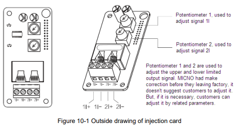
Diagram description (text version): Figure 10-1 Outside drawing of the injection card
This card provides four terminals.
1I+, 1I- is the current signal input channel 1, the correspond external channel is AI1, and function code is P0-03=2, related parameters are P4-13~P4-16.
2I+, 2I- is the current signal input channel 2, the correspond external channel is AI2, and function code is P0-04=3, related parameters are P4-17~P4-20.
The combination type of these two signals is defined by P0-07. When making the wiring connection, please be very careful of the current positive and negative poles, otherwise the system cannot work properly.

• The signal cables of injection card should be wired separately with the power supply cables; it is forbidden to wire them in parallel.
• To avoid the signals being interfered, please use shielded cables to connect the signals.
• The shield layer of signal cables should connect with the ground (like PE terminal of inverter), and it should be single-end earthed, to avoid the signals being interfered.
10.2 PG Card
10.2.1 Introduction of PG card
Card
KE600 series inverter is compatible with close-loop vector control mode. Under the close-loop vector control mode, the PG card is necessary (optional).
At present, KE600 is compatible with two kinds of PG cards; they connect with J6 on the control board.
Table 10.2 lists the brief technical specification of PG card.
Figure 10.2 shows the outline dimension of PG card, the unit is mm.
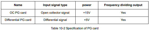
| Name | Input signal type | Power | Frequency dividing output |
|---|---|---|---|
| OC PG card | Open collector signal | +15V | Yes |
| Differential PG card | Differential signal | +5V | Yes |
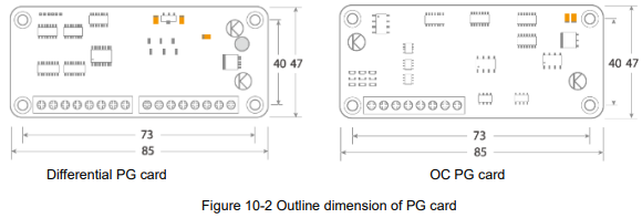
Diagram
description (text version):
Figure 10-2 Outline dimension of the PG cards (top view, mm): both the differential PG card and the OC PG card measure 85 mm in length (73 mm between mounting holes) and 47 mm in height (40 mm between mounting holes); each has a row of screw terminals along the bottom edge.10.2.2 Description of terminalsTerminals on PG card
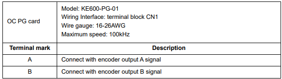
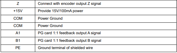


OC PG card – model KE600-PG-01; wiring interface: terminal block CN1; wire gauge: 16–26 AWG; maximum speed: 100 kHz.
| Terminal mark | Description |
|---|---|
| A | Connect with encoder output A signal |
| B | Connect with encoder output B signal |
| Z | Connect with encoder output Z signal |
| +15V | Provide 15V/100mA power |
| COM | Power ground |
| COM | Power ground |
| A1 | PG card 1:1 feedback output A signal |
| B1 | PG card 1:1 feedback output B signal |
| PE | Ground terminal of shielded wire |
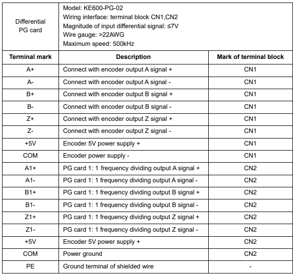
Differential PG card – model KE600-PG-02; wiring interface: terminal blocks CN1, CN2; magnitude of input differential signal: ≤ 7 V; wire gauge: > 22 AWG; maximum speed: 500 kHz.
| Terminal mark | Description | Terminal block |
|---|---|---|
| A+ | Connect with encoder output A signal + | CN1 |
| A- | Connect with encoder output A signal - | CN1 |
| B+ | Connect with encoder output B signal + | CN1 |
| B- | Connect with encoder output B signal - | CN1 |
| Z+ | Connect with encoder output Z signal + | CN1 |
| Z- | Connect with encoder output Z signal - | CN1 |
| +5V | Encoder 5V power supply + | CN1 |
| COM | Encoder power supply - | CN1 |
| A1+ | PG card 1:1 frequency dividing output A signal + | CN2 |
| A1- | PG card 1:1 frequency dividing output A signal - | CN2 |
| B1+ | PG card 1:1 frequency dividing output B signal + | CN2 |
| B1- | PG card 1:1 frequency dividing output B signal - | CN2 |
| Z1+ | PG card 1:1 frequency dividing output Z signal + | CN2 |
| Z1- | PG card 1:1 frequency dividing output Z signal - | CN2 |
| +5V | Encoder 5V power supply + | CN2 |
| COM | Power ground | CN2 |
| PE | Ground terminal of shielded wire | – |
NOTE:
• The signal cables of PG card should be wired separately with the power supply cables; it is forbidden to wire them in parallel.
• To avoid the signals being interfered, please use shielded cables to connect the signal.
• The shield layer of signal cables should connect with the ground (PE terminal on PG card), and it should be single-end earthed, to avoid the signals being interfered.
10.3 I/O Extension Card
10.3.1 Introduction of I/O card
Card
I/O extension card is used to extend input and output terminals for inverter. The model No. is KE600-DG-01. It is connected with J8 on the control board.
The I/O extension card provides the following terminals:
1, Digital Input terminals: 3 channels.
2, Digital Output terminals: 2 channels, open collector type output.
3, Relay output terminals: 1 channel, Normal Open and Normal Close.
4, Communication interface: 1 channel, standard RS485 interface.
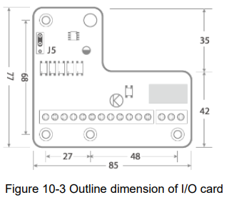
As shown in figure 10-3, jumper J5 is used to connect the terminal resistance of RS485 communication, to connect with the top two PINs, the resistance is effective.
Diagram
description (text version):
Figure 10-3 Outline dimension of the I/O extension card KE600-DG-01 (mm): L-shaped board 85 mm wide (27 mm narrow part + 48 mm wider part between holes) and 77 mm high (68 mm between mounting holes; 35 mm upper part, 42 mm lower part); jumper J5 (RS485 terminal resistor) in the upper left corner and a row of screw terminals along the bottom edge.10.3.2 Description of terminalsTerminals on I/O Extension Card
Figure 10-4 Terminals on I/O extension card
| Terminal
| Terminals
to right) |
|---|---|
| Main block | +RS485-, D8, D9, D10, Y1, Y2, COM, CME, PLC, +24V, PE |
| Relay block | T2A, T2B, T2C |
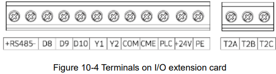
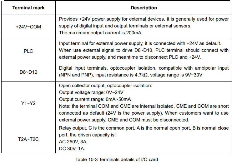
Table 10-3 Terminal details of I/O card
| Terminal mark | Description |
|---|---|
| +24V ~ COM | Provides +24 V power supply for external devices; it is generally used for power supply of digital input and output terminals or external sensors. The maximum output current is 200 mA. |
| PLC | Input terminal for external power supply; it is connected with +24V as default. When using an external signal to drive D8 ~ D10, the PLC terminal should be connected with the external power supply and disconnected from +24V. |
| D8 ~ D10 | Digital input terminals, optocoupler isolation, compatible with ambipolar input (NPN and PNP); input resistance 4.7 kΩ, voltage range 9 V ~ 30 V. |
| Y1 ~ Y2 | Open collector output, optocoupler isolation: Output voltage range: 0 V ~ 24 V Output current range: 0 mA ~ 50 mA Note: the terminals COM and CME are internally isolated; CME and COM are short-connected as default (24 V is the power supply). When customers want to use an external power supply, CME and COM must be disconnected. |
| T2A ~ T2C | Relay output: C is the common port, A is the normally open port, B is the normally closed port. Driving capacity: AC 250 V, 3 A; DC 30 V, 1 A. |
10.4 Communication Extension Card
10.4.1 Introduction of communicationCommunication card
Card
Communication extension card is used to extend the communication terminals for inverter. It is specially used for Modbus communication function, and the card adopts electrical isolation design. The communication card’s model No. is: KE600-RS485-02 It is connected with J8 on the control board.
The communication card provides the following terminals:
Communication interface: 1 channel, standard RS485 interface.
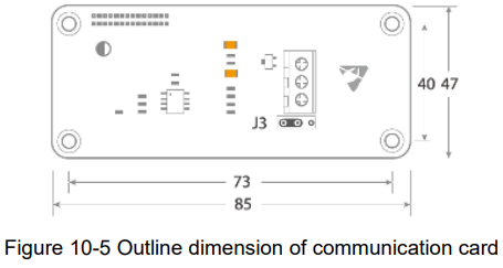
As shown in figure 10-5, jumper J3 is used to connect the terminal resistance of RS485 communication, to connect with the left two PINs, the resistance is effective.
Diagram
description (text version):
Figure 10-5 Outline dimension of the communication card KE600-RS485-02 (mm): 85 mm long (73 mm between mounting holes) and 47 mm high (40 mm between mounting holes); 3-pin terminal block on the right side and jumper J3 (RS485 terminal resistor) below it.10.4.2 Description of terminalsTerminals on Communication Extension Card
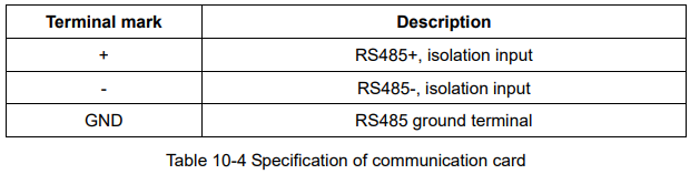
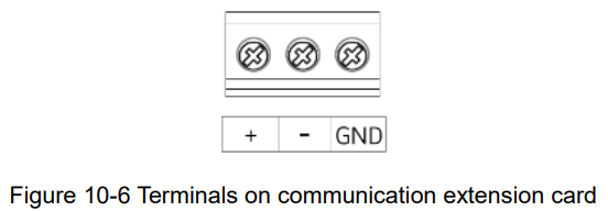
Figure 10-6 Terminals on communication extension card (left to right): +, −, GND.
| Terminal mark | Description |
|---|---|
| + | RS485+, isolation input |
| - | RS485-, isolation input |
| GND | RS485 ground terminal |
Słowa kluczowe