
6. Parameter Description – Part 6 (Groups P9–PA)
Streszczenie: Opis parametrów KE600 (część 6 z 8): zabezpieczenia i obsługa błędów (przeciążenie, utyk, auto-reset, rejestr błędów, zanik zasilania, niedociążenie, nadprędkość, odchyłka prędkości) oraz regulator PID.
EN: KE600 parameter description (part 6 of 8): protections and fault handling (overload, stall, auto reset, fault records, power loss, off-load, over-speed, speed deviation) and the PID controller.
Dotyczy: falownik wektorowy z zamkniętą pętlą Micno KE600 (zasilanie 3AC 220 V, 3AC 380 V, 3AC 660 V; moce 1,5–630 kW)
Źródło: dokumentacja producenta (Micno KE600 Series Inverter User Manual); tabele przepisane z obrazów na tekst, opisy rysunków – opracowanie Multiprojekt
Nawigacja: część 6 z 8 · poprzednia: ← Part 5 (Groups P7–P8) · następna: Part 7 (Groups PB–A0) →
Group P9 Fault and Protection
| Parameter | Name | Factory default | Setting range |
|---|---|---|---|
| P9-00 | Motor overload protection selection | 1 | 0: Invalid 1: Valid |
| P9-01 | Motor overload protection gain | 1.00 | 0.20 ~ 10.00 |
P9-00=0: Has no motor overload protection function, may cause the motor overheating damaged.
P9-00=1: The inverter judges whether the motor is overload or not according to the inverse time limit curve of motor overload protection.
The inverse time limit curve of motor overload protection: 220%×(P9-01)×motor rated current, lasts for one minute, the overload fault would be reported; 150%×(P9-01)×motor rated current, lasts for 60 minutes, the overload fault would be reported.
Please set P9-01 according to the motor overload ability. If the parameter is too big, the motor will over heat damage without alarming.
| Parameter | Name | Factory default | Setting range |
|---|---|---|---|
| P9-02 | Motor overload pre-warning coefficient | 80% | 50% ~ 100% |
For safe consideration, there is a pre-warming signal sent to the control system via DO before the motor overload fault protection, the pre-warming coefficient is used to confirm the extent of pre-warming before the motor overload protection. The bigger the parameter is, the smaller the pre-warming lead is.
After the accumulated output current is bigger than (P9-02)*overload inverse time limit curve, DO outputs “motor overload pre-warming” ON signal.
| Parameter | Name | Factory default | Setting range |
|---|---|---|---|
| P9-03 | Over-voltage stall gain | 0 | 0 (no over-voltage stall) ~ 100 |
| P9-04 | Over-voltage stall protection voltage | 130% | 120% ~ 150% (three phase) |
During deceleration, after DC bus voltage exceeds over-voltage stall protection voltage, the inverter stops deceleration & runs with the current frequency; continue decelerating after bus voltage drops.
Over-voltage stall gain is used to adjust the suppression over-voltage capacity during deceleration. The bigger this value is, the stronger the capacity is. Under the precondition of no over-voltage, please set the gain as small as possible.
For the load with small inertia, the value should be small. Otherwise, the dynamic response of the system will be slow. For the load with big inertia, the value should be big. Otherwise, the suppression result will be poor, and over voltage fault may occur.
When the value is 0, the over voltage stall function is invalid.
| Parameter | Name | Factory default | Setting range |
|---|---|---|---|
| P9-05 | Over-current stall gain | 20 | 0 ~ 100 |
| P9-06 | Over-current stall protection current | 160% | 100% ~ 200% |
During the inverter ACC/DEC, when the output current exceeds over-current stall protection current, the inverter stops ACC/DEC, runs with the current frequency, continue ACC/DEC after the output current is reduced.
Over-current stall gain is used to adjust the suppression over-current capacity during ACC/DEC. The bigger this value is, the stronger the capacity is. Under the precondition of no over-current, please set the gain as small as possible.
For the load with small inertia, the value should be small. Otherwise, the dynamic response of the system will be slow. For the load with big inertia, the value should be big. Otherwise, the suppression result will be poor, and over-current fault may occur.
When the value is 0, the over-voltage stall function is invalid.
| Parameter | Name | Factory default | Setting range |
|---|---|---|---|
| P9-07 | Short circuit to ground protection selection when power-on | 1 | 0: Invalid 1: Valid |
It is used to check if the motor is short circuit to ground when the inverter is power on.
If the function is valid, the inverter UVW terminals have output voltage after power on for a while.
| Parameter | Name | Factory default | Setting range |
|---|---|---|---|
| P9-08 | Fast current limitation | 1 | 0: Disable 1: Enable |
| P9-09 | Fault auto reset times | 0 | 0 ~ 5 |
After the inverter fails in running process, the inverter stops its output; then performs auto fault reset and continues running after the reset interval defined in P9-11.
P9-09 is used to set fault auto reset times. After this value is exceeded, the inverter will keep fault status.
When the fault auto reset time is setup to 0, there is no auto-reset function, and only manual reset can be done
| Parameter | Name | Factory default | Setting range |
|---|---|---|---|
| P9-10 | Faulty HDO action selection during fault auto resetting | 0 | 0: No action 1: Action |
If fault auto reset function is valid, during fault auto resetting, fault reply action or not can be set via P9-10.
| Parameter | Name | Factory default | Setting range |
|---|---|---|---|
| P9-11 | Fault auto reset interval | 1.0s | 0.1s ~ 100.0s |
The waiting time of the inverter from the fault alarm to auto reset.
| Parameter | Name | Factory default | Setting range |
|---|---|---|---|
| P9-12 | Input phase failure protection selection | 0 | 0: Invalid 1: Valid |
KE600 series inverter has no input phase failure protection function at present, whatever P9-12 is set to 0 or 1, this function is invalid.
| Parameter | Name | Factory default | Setting range |
|---|---|---|---|
| P9-13 | Output phase failure protection selection | 1 | 0: Invalid 1: Valid |
Select to protect output phase failure or not.
Fault record – fault types
| Parameter | Name | Range |
|---|---|---|
| P9-14 | The first fault type | 0 ~ 50 |
| P9-15 | The second fault type | 0 ~ 50 |
| P9-16 | The third (last) fault type | 0 ~ 50 |
It is used to record the fault types of last three times: 0 indicates no fault, please refer to Chapter 8 for solutions.
Fault record – details of the last three faults
| Parameter | Name | Description |
|---|---|---|
| P9-17 | The third fault frequency | The last fault frequency |
| P9-18 | The third fault current | The last fault current |
| P9-19 | The third (last) fault bus voltage | The last fault bus voltage |
| P9-20 | The third fault type output terminal status | The last fault type output terminal status, sequence: when the input terminal is ON, the corresponding binary bit is 1, when the input terminal is OFF, the corresponding binary bit is 0. All DI statuses are displayed as decimal numbers. |
| P9-21 | The third fault type output terminal | The last fault type output terminal status, sequence: when the input terminal is ON, the corresponding binary bit is 1, when the input terminal is OFF, the corresponding binary bit is 0. All DO statuses are displayed as decimal numbers. |
| P9-22 | The third fault inverter status | The last fault inverter status |
| P9-23 | The third (last) fault power on time | The last fault power on time |
| P9-24 | The third (last) fault running time | The last fault running time |
| P9-27 | The second fault frequency | Same as P9-17 ~ P9-24 |
| P9-28 | The second fault current | Same as P9-17 ~ P9-24 |
| P9-29 | The second fault bus voltage | Same as P9-17 ~ P9-24 |
| P9-30 | The second fault input terminal status | Same as P9-17 ~ P9-24 |
| P9-31 | The second fault output terminal status | Same as P9-17 ~ P9-24 |
| P9-32 | The second fault inverter status | Same as P9-17 ~ P9-24 |
| P9-33 | The second fault power on time | Same as P9-17 ~ P9-24 |
| P9-34 | The second fault running time | Same as P9-17 ~ P9-24 |
| P9-37 | The first fault frequency | Same as P9-17 ~ P9-24 |
| P9-38 | The first fault current | Same as P9-17 ~ P9-24 |
| P9-39 | The first fault bus voltage | Same as P9-17 ~ P9-24 |
| P9-40 | The first fault input terminal status | Same as P9-17 ~ P9-24 |
| P9-41 | The first fault output terminal status | Same as P9-17 ~ P9-24 |
| P9-42 | The first fault inverter status | Same as P9-17 ~ P9-24 |
| P9-43 | The first fault power on time | Same as P9-17 ~ P9-24 |
| P9-44 | The first fault running time | Same as P9-17 ~ P9-24 |
| Parameter | Name | Factory default | Setting range |
|---|---|---|---|
| P9-47 | Fault protection action selection 1 | 00000 | Units place – motor overload (E-11): 0: Coast to stop 1: Dec-to-stop 2: Keep running Tens place – input phase failure (E-12) (same as units place) Hundreds place – output phase failure (E-13) (same as units place) Thousands place – external fault (E-14) (same as units place) Ten thousands place – communication fault (E-15) (same as units place) |
| P9-48 | Fault protection action selection 2 | 00000 | Units place – reserved Tens place – E²PROM W/R fault (E-21): 0: Coast to stop 1: Dec-to-stop Hundreds place – reserved Thousands place – reserved Ten thousands place – running time arrival (E-26) (same as units place of P9-47) |
| P9-49 | Fault protection action selection 3 | 00000 | Units place – customized fault 1 (E-27) (same as units place of P9-47) Tens place – customized fault 2 (E-28) (same as units place of P9-47) Hundreds place – power-on time arrival (E-29) (same as P9-47 units place) Thousands place – off load (E-30): 0: Coast to stop 1: Dec-to-stop 2: Deceleration to 7% of motor rated power, then keep running; run at setting frequency when no off-load Ten thousands place – PID feedback lost when running (E-31) (same as units place of P9-47) |
| Parameter | Name | Factory default | Setting range |
|---|---|---|---|
| P9-50 | Fault protection action selection 4 | 00000 | Units place – speed deviation oversize (E-42) (same as units place of P9-47) Tens place – motor over speed (E-43) (same as units place of P9-47) Hundreds place – reserved Thousands place – reserved Ten thousands place – reserved |
When the selection is “Coast to stop”, the inverter shows E-** and stops directly.
When the selection is “Dec- to-stop”, the inverter shows A-** and decelerates to stop, then shows E-** after stopping.
When the selection is “keep running”, the inverter shows A-** and keeps running, the running frequency is set by P9-54.
| Parameter | Name | Factory default | Setting range |
|---|---|---|---|
| P9-54 | Running frequency selection continuously when fault | 0 | 0: Run at current running frequency 1: Run at setting frequency 2: Run at upper limit frequency 3: Run at lower limit frequency 4: Run at abnormal backup frequency |
| P9-55 | Abnormal backup frequency | 100.0% | 60.0% ~ 100.0% |
When a fault happens during running and the fault process mode is keep running, the inverter shows A-** with the frequency set by P9-54.
When the inverter is running with the abnormal backup frequency, the value set by P9-55 corresponds to maximum frequency percentage.
| Parameter | Name | Factory default | Setting range |
|---|---|---|---|
| P9-59 | Instantaneous power-off action | 0 | 0: Invalid 1: Deceleration 2: Dec-to-stop |
| P9-60 | Instantaneous power-off recover judgment voltage | 90.0% | 80.0% ~ 100.0% |
| P9-61 | Instantaneous power-off voltage recover judgment time | 0.50s | 0.00s ~ 100.00s |
| P9-62 | Instantaneous power-off action judgment voltage | 80.0% | 60.0% ~ 100.0% (standard bus voltage) |
The function is that, when instantaneous power off or voltage drops suddenly, the inverter will reduce output speed to decrease compensation voltage for DC bus which is generated by the load feedback energy, so that keep the inverter running.
P9-59=1: When instantaneous power off or voltage drops suddenly, the inverter decelerates, when bus voltage returns to normal, the inverter accelerates to the setting frequency and runs. Normal bus voltage lasts for longer than the time set by P9-61 means that bus voltage returns to normal.
P9-59=2: When instantaneous power off or voltage drops suddenly, the inverter decelerates to stop.
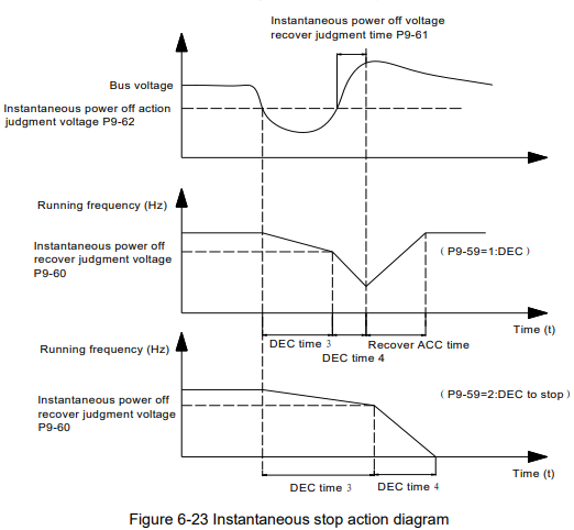
Diagram description (text version): Figure 6-23 Instantaneous power-off action: when the bus voltage drops below the action judgment voltage P9-62, the inverter decelerates (DEC time 3, then DEC time 4 below the recover judgment level P9-60). With P9-59 = 1 (deceleration), if the bus voltage recovers and stays above the recover level for the judgment time P9-61, the inverter re-accelerates to the original frequency (recover ACC time). With P9-59 = 2 (DEC to stop), the inverter decelerates to stop.
| Parameter | Name | Factory default | Setting range |
|---|---|---|---|
| P9-63 | Off-load protection selection | 0 | 0: Invalid 1: Valid |
| P9-64 | Off-load detection level | 10.0% | 0.0% ~ 100.0% (motor rated current) |
| P9-65 | Off-load detection time | 1.0s | 0.0s ~ 60.0s |
If off-load protection function is valid, when the output current is smaller than off-load detection level P9-64, lasts for longer than off-load detection time P9-65, the output frequency will reduce to 7% of the rated frequency automatically. During off-load protection, if load recovers, the inverter will recover and run with the setting frequency automatically.
| Parameter | Name | Factory default | Setting range |
|---|---|---|---|
| P9-67 | Over speed detection value | 20.0% | 0.0 ~ 50.0% (maximum frequency) |
| P9-68 | Over speed detection time | 1.0s | 0.0s: no detection 0.1 ~ 60.0s |
These two parameters are only valid under the close-loop vector control mode.
If the real detected speed of motor is bigger than the maximum frequency, and the excess value is bigger than the setting of P9-67, after the duration time of P9-68, the inverter will give failure information of “E-43”, and then the inverter will give response according to the set of P9-50.
If the P9-68 is set as 0.0s, there is no protection for over speed.
| Parameter | Name | Factory default | Setting range |
|---|---|---|---|
| P9-69 | Speed deviation oversize detection value | 20.0% | 0.0 ~ 50.0% (maximum frequency) |
| P9-70 | Speed deviation oversize detection time | 5.0s | 0.0s: no detection 0.1 ~ 60.0s |
These two parameters are only valid under the close-loop vector control mode.
If the real detected speed of motor is different with the setting frequency, and the deviation is bigger than the setting value of P9-69, after the duration time of P9-70, the inverter will give failure information of “E-42”, and then the inverter will give response according to the set of P9-50.
If the P9-69 is set as 0.0s, there is no protection for speed deviation.
Group PA PID Function
PID control is a common used method in process control, such as flow, pressure and temperature control.
The principle is firstly to detect the bias between preset/given value and feedback value, then calculate output frequency of inverter according to proportional gain, integral and differential time. Please refer to following figure.
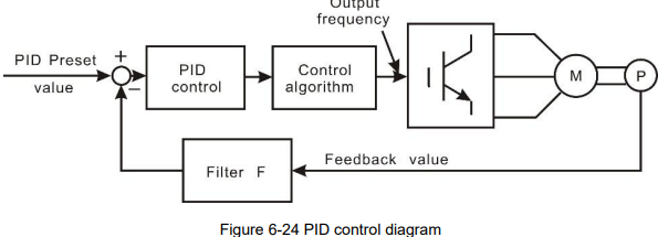
Diagram description (text version): Figure 6-24 PID control: the PID preset value minus the filtered feedback value (filter F) is fed to the PID controller; its output goes through the control algorithm to the inverter output frequency driving the motor M and pump P; the measured process value returns as the feedback value.
| Parameter | Name | Factory default | Setting range |
|---|---|---|---|
| PA-00 | PID given source | 0 | 0: PA-01 1: AI1 2: AI2 3: Keypad potentiometer 4: High speed pulse HDI 5: Communication 6: Multi-step command |
| PA-01 | PID keypad given | 0.0 | 0.0 ~ PA-04 (PID given feedback range) |
This parameter is used to select the given channel of PID target value
This value is an actual physical quantity. It must correspond to the measure range. For example, if the PID keypad given value is 0.3Mpa, PA-01 should be set to 3.0.
| Parameter | Name | Factory default | Setting range |
|---|---|---|---|
| PA-02 | PID feedback source | 0 | 0: AI1 1: AI2 2: Keypad potentiometer 3: AI1 − AI2 4: High speed pulse HDI 5: Communication 6: AI1 + AI2 7: MAX (|AI1|, |AI2|) 8: MIN (|AI1|, |AI2|) |
These parameters are used to select PID given and feedback source.
Notice: Given value and feedback value of PID are percentage values.
100% of given value is corresponding to 100% of feedback value.
Given source and feedback source must not be same, otherwise PID will be malfunction
| Parameter | Name | Factory default | Setting range |
|---|---|---|---|
| PA-03 | PID action direction | 0 | 0: Positive 1: Negative |
0: Positive. When the feedback value is greater than the given value, output frequency will be decreased, such as tension control in winding application.
1: Negative. When the feedback value is greater than the given value, output frequency will be increased, such as tension control in unwinding application
| Parameter | Name | Factory default | Setting range |
|---|---|---|---|
| PA-04 | PID given/feedback range | 100.0 | PA-01 (PID given through keypad) ~ 1000.0 |
PID given feedback range is a non-dimensional unit. It must correspond to the actual measure range. For example, if the measure range of the pressure meter is 1.0 Mpa, then this parameter should be set to 10.
| Parameter | Name | Factory default | Setting range |
|---|---|---|---|
| PA-05 | Proportional gain Kp1 | 20.0 | 0.0 ~ 100.0 |
| PA-06 | Integration time Ti1 | 2.00s | 0.01s ~ 10.00s |
| PA-07 | Differential time Td1 | 0.000s | 0.00 ~ 10.000 |
Proportional gain Kp1: It decides the adjustment intensity of the whole PID regulator. The higher the Kp1 is, the stronger the adjustment intensity is. When this parameter is 100, indicating the deviation between PID feedback value and given value is 100%, the adjustment amplitude of the PID regulator on the output frequency command is maximum frequency.
Integration time Ti1: It decides the intensity of the integration adjustment of PID regulator. The shorter the integration time is, the stronger the adjustment intensity is. Integration time is the time within which the adjustment value reaches maximum frequency when the deviation between PID feedback value and given value is 100%.
Differential time Td1: It decides the intensity of the deviation change rate of PID regulator. The longer the differential time is, the stronger the adjustment intensity is. Differential time is the time within which if the feedback value changes 100%, the adjustment value reaches maximum frequency.
| Parameter | Name | Factory default | Setting range |
|---|---|---|---|
| PA-08 | Cut-off frequency of PID reverse | 0.00Hz | 0.00 ~ P0-10 (maximum frequency) |
In some situation, only when PID output frequency is negative (inverter reverse), PID can make given value and feedback value in a same status. But the reverse frequency cannot be too high for some applications. The reverse frequency upper limit is determined by PA-08.
| Parameter | Name | Factory default | Setting range |
|---|---|---|---|
| PA-09 | PID deviation limit | 0.0% | 0.0% ~ 100.0% |
When the deviation between PID given value and feedback value is smaller than PA-09, PID stops adjustment. The output frequency is stable when the deviation is small, which is suitable for some close loop control applications.
| Parameter | Name | Factory default | Setting range |
|---|---|---|---|
| PA-10 | PID differential amplitude | 0.10% | 0.00% ~ 100.00% |
| PA-11 | PID given filter time | 0.00s | 0.00s ~ 650.00s |
PID given filter time is the time that PID given value changes from 0.0% to 100.0%.
When PID given is changing, PID given value linearly changes according to the given filter time, so as to reduce the adverse effect of the system caused by the given sudden change.
| Parameter | Name | Factory default | Setting range |
|---|---|---|---|
| PA-12 | PID feedback filter time | 0.00s | 0.00s ~ 60.00s |
| PA-13 | PID output filter time | 0.00s | 0.00s ~ 60.00s |
PA-12 is used to filter the PID feedback value, this filter can improve anti-interference capability of feedback value, but will bring the response performance of the process close loop system down.
PA-13 is used to filter the PID output frequency, this filter will reduce the sudden change of the inverter output frequency, but also will bring the response performance of the process close loop system down.
| Parameter | Name | Factory default | Setting range |
|---|---|---|---|
| PA-15 | Proportional gain Kp2 | 20.0 | 0.0 ~ 100.0 |
| PA-16 | Integration time Ti2 | 2.00s | 0.01s ~ 10.00s |
| PA-17 | Differential time Td2 | 0.000s | 0.00 ~ 10.000 |
| PA-18 | PID parameter switching condition | 0 | 0: No switching 1: Switching via terminals 2: Automatic switching according to the deviation |
| PA-19 | PID parameter switching deviation 1 | 20.0% | 0.0% ~ PA-20 |
| Parameter | Name | Factory default | Setting range |
|---|---|---|---|
| PA-20 | PID parameter switching deviation 2 | 80.0% | PA-19 ~ 100.0% |
In some applications, one group PID parameter is not enough, different PID parameters would be adopted according to the situation.
The function codes are used to switch two groups PID parameter. The setting mode of the regulator parameters PA-15~PA-17 is similar as PA-05~PA-07’s.
Two groups PID parameter can be switched via DI terminal, or switched according to PID deviation automatically.
When selection is automatic switching: when the deviation absolute value between given and feedback is smaller than PA-19 (PID parameter switching deviation 1), PID parameter selection is group 1. When the deviation absolute value between given and feedback is bigger than PA-20 (PID parameter switching deviation 2), PID parameter selection is group 2. When the deviation absolute value between given and feedback is between PA-19 and PA-20, PID parameter is the linear interpolation of two groups PID parameter, showed as figure 6-25.
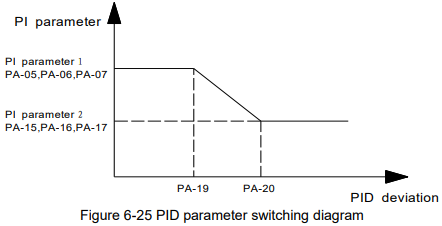
Diagram description (text version): Figure 6-25 PID parameter switching: when the PID deviation is below PA-19 the controller uses PI parameter set 1 (PA-05, PA-06, PA-07); above PA-20 it uses set 2 (PA-15, PA-16, PA-17); between PA-19 and PA-20 the parameters change linearly from set 1 to set 2.
| Parameter | Name | Factory default | Setting range |
|---|---|---|---|
| PA-21 | PID initial value | 0.0% | 0.0% ~ 100.0% |
| PA-22 | PID initial value holding time | 0.00s | 0.00s ~ 360.00s |
When starting, PID output is PID initial value (PA-21), lasts for PID initial value holding time (PA-22), PID starts close-loop regulate calculating.
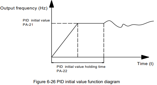
Diagram description (text version): Figure 6-26 PID initial value: after start the output frequency ramps to the PID initial value PA-21 and is held there for the holding time PA-22; after that the PID regulation takes over and the frequency follows the PID output.
| Parameter | Name | Factory default | Setting range |
|---|---|---|---|
| PA-23 | Forward maximum value between two output deviations | 1.00% | 0.00% ~ 100.00% |
| PA-24 | Reverse maximum value between two output deviations | 1.00% | 0.00% ~ 100.00% |
This function is used to limit the difference between PID output two bats (2ms/bat), so as to against PID output changing too fast, make the inverter run stably.
PA-23 and PA-24 correspond to the maximum of the output deviation absolute value when forward and reverse, respectively.
| Parameter | Name | Factory default | Setting range |
|---|---|---|---|
| PA-25 | PID integration attribute | 00 | Units place – integration separate: 0: Invalid 1: Valid Tens place – stop integrating or not after output reaches limit: 0: Continue integrating 1: Stop integrating |
Integration separation:
If integration separation is valid, when multifunctional digital DI integration pause (function 22) is valid, PID integration stop calculating, PID is only valid when proportional and differential action.
When integration separation is invalid, whatever multifunctional digital DI is valid or not, integration separation is invalid.
Stop integrating or not after output reach limit:
After PID calculation output reaches the maximum or minimum, whether stop integral action or not can be selected. If the selection is stop integrating, PID integration will stop calculating, which may help to reduce PID overshoot.
| Parameter | Name | Factory default | Setting range |
|---|---|---|---|
| PA-26 | PID feedback lost detection value | 0.0% | 0.0%: no judgment for feedback lost 0.1% ~ 100.0% |
| PA-27 | PID feedback lost detection time | 1.0s | 0.0s ~ 20.0s |
The parameters are used to judge whether PID feedback lost or not.
When PID feedback is smaller than feedback lost detection value (PA-26), lasts for longer than PID feedback lost detection time (PA-27), the inverter alarms fault E-31, and handles according to the chose fault process mode.
| Parameter | Name | Factory default | Setting range |
|---|---|---|---|
| PA-28 | PID stop calculation | 1 | 0: No calculation when stop 1: Calculation when stop |
This parameter is used to select PID stop status & whether PID continues calculating or not. For normal applications, PID should stop calculating when stop.
Słowa kluczowe
Micno KE600, opis parametrów, parameter description, P9, PA, zabezpieczenia, protection, przeciążenie, overload, auto reset, rejestr błędów, fault record, nadprędkość, over speed, PID