
6. Parameter Description – Part 7 (Groups PB–A0)
Streszczenie: Opis parametrów KE600 (część 7 z 8): funkcja wobble, długość i licznik, prędkości wielostopniowe i prosty PLC, zarządzanie parametrami (hasło, inicjalizacja) oraz sterowanie momentem.
EN: KE600 parameter description (part 7 of 8): wobble function, length and counting, multi-step speeds and simple PLC, parameter management (password, initialization) and torque control.
Dotyczy: falownik wektorowy z zamkniętą pętlą Micno KE600 (zasilanie 3AC 220 V, 3AC 380 V, 3AC 660 V; moce 1,5–630 kW)
Źródło: dokumentacja producenta (Micno KE600 Series Inverter User Manual); tabele przepisane z obrazów na tekst, opisy rysunków – opracowanie Multiprojekt
Group PB Wobble Frequency, Fixed Length, Counting
The wobble frequency function is suitable for textile, chemical fiber industries, and the applications which require traversing and winding functions.
The wobble frequency function means that the output frequency of the inverter wobbles up and down with the setting frequency as the center. The trace of running frequency at the time axis is shown in the figure below, of which the wobble amplitude is set by PB-00 and PB-01. When PB-01 is set to 0, indicating the wobble amplitude is 0, the wobble frequency is disabled.
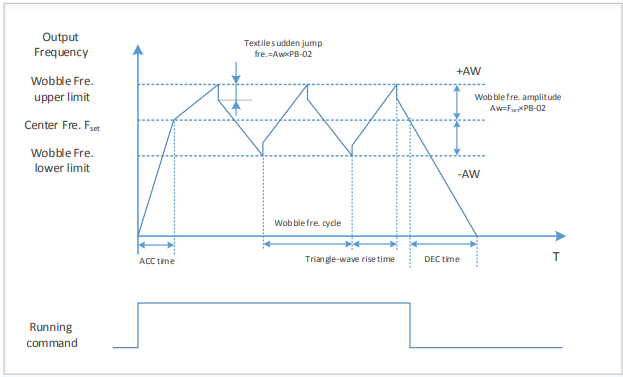
Diagram description (text version): Figure 6-27 Wobble frequency operation: after the running command the output accelerates (ACC time) to the center frequency Fset and then oscillates in a triangle wave between the wobble upper limit (+AW) and lower limit (−AW); the wobble amplitude AW = Fset × PB-01 (labelled “Fset × PB-02” in the figure). The wobble cycle and the triangle-wave rise time define the wave shape; at each peak the frequency drops by the textile sudden jump amplitude (AW × PB-02). When the running command is removed, the inverter decelerates (DEC time).
| Parameter | Name | Factory default | Setting range |
|---|---|---|---|
| PB-00 | Wobble frequency amplitude setting mode | 0 | 0: Relative to the center frequency 1: Relative to maximum frequency |
This parameter is used to select the reference value of the wobble amplitude.
0: Relative to the center frequency (P0-07: frequency source selection), and it is variable wobble amplitude system. The wobble amplitude changes with the center frequency (setting frequency).
1: Relative to the maximum frequency (P0-10) and it is fixed wobble amplitude system. The wobble amplitude is fixed.
| Parameter | Name | Factory default | Setting range |
|---|---|---|---|
| PB-01 | Wobble frequency amplitude | 0.0% | 0.0% ~ 100.0% |
| PB-02 | Sudden jump frequency amplitude | 0.0% | 0.0% ~ 50.0% |
This parameter is used to determine the values of wobble amplitude and sudden jump frequency. The wobble frequency is limited by the frequency upper limit and frequency lower limit.
The wobble amplitude is relative to the central frequency (variable wobble amplitude, select PB-00=0): wobble amplitude: AW=frequency source: P0-07 × wobble amplitude: PB-01.
The wobble amplitude is relative to the maximum frequency (fixed wobble amplitude, select PB-00=1): wobble amplitude: AW=maximum frequency: P0-10 × wobble amplitude: PB-01.
Sudden jump frequency=wobble amplitude: AW × sudden jump frequency amplitude: PB-02. That is the value of sudden jump frequency relative to the wobble amplitude when the wobble frequency is running.
If the wobble amplitude relative to the central frequency (variable wobble amplitude, select PB-00=0) is selected, the sudden jump frequency is a variable value.
If the wobble amplitude relative to the maximum frequency (fixed wobble amplitude, select PB-00=1) is selected, the sudden jump frequency is a fixed value.
| Parameter | Name | Factory default | Setting range |
|---|---|---|---|
| PB-03 | Wobble frequency cycle | 10.0s | 0.1s ~ 3000.0s |
| PB-04 | Triangle-wave rise time of wobble frequency | 50.0% | 0.1% ~ 100.0% |
Wobble frequency cycle: It refers to the time of a complete cycle of wobble frequency.
PB-04 is relative to the percentage of PB-03.
Triangular wave rise time = PB-03 × PB-04 (unit: s)
Triangular wave fall time = PB-03 × (1-PB-04) (unit: s)
| Parameter | Name | Factory default | Setting range |
|---|---|---|---|
| PB-05 | Setting length | 1000m | 0m ~ 65535m |
| PB-06 | Actual length | 0m | 0m ~ 65535m |
| PB-07 | Number of pulses per meter | 100.0 | 0.1 ~ 6553.5 |
The parameters are used in fixed length control.
Length information can be collected via input terminals, PB-06= the collected number of pulses/PB 07.
When PB-06 is longer than PB-05, DO outputs “length arrival” ON signal.
During fixed length control, length reset operation can be done by set DI terminal function to 28, refers to P4-00~P4-06 for details.
The relative input terminal function need to be set to 27 (length counting input) for applications, HDI must be used when the pulse frequency is high.
| Parameter | Name | Factory default | Setting range |
|---|---|---|---|
| PB-08 | Setting counting value | 1000 | 1 ~ 65535 |
| PB-09 | Designated counting value | 1000 | 1 ~ 65535 |
The counting value can be collected via digital input terminals. The relative input terminal function need to be set to 25 (Counter input) for applications, HDI must be used when the pulse frequency is high.
When the counting value reaches PB-08, DO outputs “setting counting value arrival” ON signal, then the counter will stop counting.
When the counting value reaches PB-09, DO outputs “designated counting value” ON signal. The counter will continue counting till the “setting counting value” is reached.
PB-09 should not exceed PB-08.
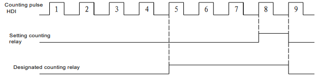
Diagram description (text version): Figure 6-28 Setting counting value arrival and designated counting value arrival: counting pulses on HDI are numbered 1, 2, 3 …; in the example the designated counting relay switches ON at pulse 5 (designated value) and the setting counting relay switches ON at pulse 8 (setting value).
Figure 6-28 Setting counting value arrival and designated counting value arrival function diagram
Group PC Multi-step Command and Simple PLC Function
The multi-step command of KE600 series inverter has more functions than normal multi-step speed.
Besides multi-step speed functions, it can be used as the given source of the process PID.
| Parameter | Name | Factory default | Setting range |
|---|---|---|---|
| PC-00 | Multi-step command 0 | 0.0% | -100.0% ~ 100.0% |
| PC-01 | Multi-step command 1 | 0.0% | -100.0% ~ 100.0% |
| PC-02 | Multi-step command 2 | 0.0% | -100.0% ~ 100.0% |
| PC-03 | Multi-step command 3 | 0.0% | -100.0% ~ 100.0% |
| PC-04 | Multi-step command 4 | 0.0% | -100.0% ~ 100.0% |
| PC-05 | Multi-step command 5 | 0.0% | -100.0% ~ 100.0% |
| PC-06 | Multi-step command 6 | 0.0% | -100.0% ~ 100.0% |
| PC-07 | Multi-step command 7 | 0.0% | -100.0% ~ 100.0% |
| PC-08 | Multi-step command 8 | 0.0% | -100.0% ~ 100.0% |
| PC-09 | Multi-step command 9 | 0.0% | -100.0% ~ 100.0% |
| PC-10 | Multi-step command 10 | 0.0Hz (as in the source) | -100.0% ~ 100.0% |
| PC-11 | Multi-step command 11 | 0.0% | -100.0% ~ 100.0% |
| PC-12 | Multi-step command 12 | 0.0% | -100.0% ~ 100.0% |
| PC-13 | Multi-step command 13 | 0.0% | -100.0% ~ 100.0% |
| PC-14 | Multi-step command 14 | 0.0% | -100.0% ~ 100.0% |
| PC-15 | Multi-step command 15 | 0.0% | -100.0% ~ 100.0% |
Multi-step command can be used in two situations: as frequency source or as the setting source of the process PID.
In two situations, the dimension of the multi-step command is relative value, range -100.0%~100.0%,
When as the frequency source is the percentage of the relative maximum frequency, multi-step command as PID setting source does not need dimension switching, because PID given is relative value. Multi-step command switches selection according to the different status of multifunctional digital D, please refer to P4 group for details.
| Parameter | Name | Factory default | Setting range |
|---|---|---|---|
| PC-16 | PLC running mode | 0 | 0: Stop after one cycle 1: Keep last frequency after one cycle 2: Circular running |
When frequency source is set by simple PLC, the symbols of PC-00 ~ PC-15 determines the running direction, the inverter run reverse if they are negative values.
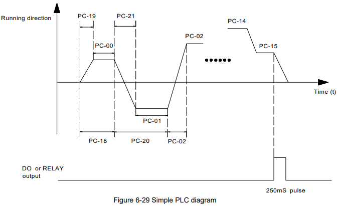
Diagram description (text version): Figure 6-29 Simple PLC: the inverter runs step by step through multi-step commands PC-00, PC-01, PC-02 … PC-15; each step has its own running time (PC-18, PC-20, PC-22 …) and ACC/DEC time (PC-19, PC-21 …), and the sign of the command sets the running direction (e.g. PC-01 negative = reverse). After the last step (PC-15) a 250 ms pulse is given on the DO or relay output (PLC cycle completed).
0: Stop after one cycle: Inverter stops automatically as soon as it completes one cycle, and It needs run command to start again.
1: keep last frequency after one cycle: Inverter holds frequency and direction of last phase after one cycle.
2: Circular running: Inverter continues to run cycle by cycle until receive a stop command.
| Parameter | Name | Factory default | Setting range |
|---|---|---|---|
| PC-17 | Simple PLC storage selection when power-down | 00 | Units place – when power-off: 0: Not store 1: Store Tens place – when stop: 0: Not store 1: Store |
PLC storage when power-off means the last PLC running phase and running frequency are memorized before power-off, keep running from the memory status after power-on next time.
When selection is “not store”, restart PLC process after power-on each time. “PLC storage when stop” means the last PLC running phase and running frequency are memorized when stopping, keep running with the memory status after power-on next time. When selection is “not store”, restart PLC process after power-on each time.
| Parameter | Name | Factory default | Setting range |
|---|---|---|---|
| PC-18 | 0th phase running time | 0.0s (m) | 0.0s (m) ~ 6500.0s (m) |
| PC-19 | 0th phase ACC/DEC time selection | 0 | 0 ~ 3 |
| PC-20 | 1st phase running time | 0.0s (m) | 0.0s (m) ~ 6500.0s (m) |
| PC-21 | 1st phase ACC/DEC time selection | 0 | 0 ~ 3 |
| PC-22 | 2nd phase running time | 0.0s (m) | 0.0s (m) ~ 6500.0s (m) |
| PC-23 | 2nd phase ACC/DEC time selection | 0 | 0 ~ 3 |
| PC-24 | 3rd phase running time | 0.0s (m) | 0.0s (m) ~ 6500.0s (m) |
| PC-25 | 3rd phase ACC/DEC time selection | 0 | 0 ~ 3 |
| PC-26 | 4th phase running time | 0.0s (m) | 0.0s (m) ~ 6500.0s (m) |
| PC-27 | 4th phase ACC/DEC time selection | 0 | 0 ~ 3 |
| PC-28 | 5th phase running time | 0.0s (m) | 0.0s (m) ~ 6500.0s (m) |
| PC-29 | 5th phase ACC/DEC time selection | 0 | 0 ~ 3 |
| PC-30 | 6th phase running time | 0.0s (m) | 0.0s (m) ~ 6500.0s (m) |
| PC-31 | 6th phase ACC/DEC time selection | 0 | 0 ~ 3 |
| PC-32 | 7th phase running time | 0.0s (m) | 0.0s (m) ~ 6500.0s (m) |
| PC-33 | 7th phase ACC/DEC time selection | 0 | 0 ~ 3 |
| PC-34 | 8th phase running time | 0.0s (m) | 0.0s (m) ~ 6500.0s (m) |
| PC-35 | 8th phase ACC/DEC time selection | 0 | 0 ~ 3 |
| PC-36 | 9th phase running time | 0.0s (m) | 0.0s (m) ~ 6500.0s (m) |
| PC-37 | 9th phase ACC/DEC time selection | 0 | 0 ~ 3 |
| PC-38 | 10th phase running time | 0.0s (m) | 0.0s (m) ~ 6500.0s (m) |
| PC-39 | 10th phase ACC/DEC time selection | 0 | 0 ~ 3 |
| PC-40 | 11th phase running time | 0.0s (m) | 0.0s (m) ~ 6500.0s (m) |
| PC-41 | 11th phase ACC/DEC time selection | 0 | 0 ~ 3 |
| PC-42 | 12th phase running time | 0.0s (m) | 0.0s (m) ~ 6500.0s (m) |
| PC-43 | 12th phase ACC/DEC time selection | 0 | 0 ~ 3 |
| PC-44 | 13th phase running time | 0.0s (m) | 0.0s (m) ~ 6500.0s (m) |
| PC-45 | 13th phase ACC/DEC time selection | 0 | 0 ~ 3 |
| PC-46 | 14th phase running time | 0.0s (m) | 0.0s (m) ~ 6500.0s (m) |
| Parameter | Name | Factory default | Setting range |
|---|---|---|---|
| PC-47 | 14th phase ACC/DEC time selection | 0 | 0 ~ 3 |
| PC-48 | 15th phase running time | 0.0s (m) | 0.0s (m) ~ 6500.0s (m) |
| PC-49 | 15th phase ACC/DEC time selection | 0 | 0 ~ 3 |
| PC-50 | PLC running time unit | 0 | 0: s (second) 1: m (minute) |
| PC-51 | Multi-step command 0 given mode | 0 | 0: PC-00 1: AI1 2: AI2 3: Keypad potentiometer 4: HDI high speed pulse 5: PID control 6: Keypad setting frequency (P0-08), UP/DN can be modified |
The given channel of multi-step command 0 is determined by this parameter.
Multi-step command 0 has many selections besides PC-00, which is conveniently for switching between multi-step command and other given modes. When the frequency source is set by multi-step command or simple PLC, it can achieve switching two frequency sources easily.
Group PD Communication Parameters
Refer to the Communication Protocol for details.
Group PP Function Code Management
| Parameter | Name | Factory default | Setting range |
|---|---|---|---|
| PP-00 | User password | 0 | 0 ~ 65535 |
Any non-zero number can be set, and then the password protection function will be enabled. When user enters into the menu next time, “-----” will be displayed, please input the right password, otherwise the parameters cannot be checked or modified.
0000: Clear the previous password and disable the password protection function
| Parameter | Name | Factory default | Setting range |
|---|---|---|---|
| PP-01 | Parameter initialization | 0 | 0: No operation 1: Restore factory default, but not including motor parameters 2: Clear the fault record |
1. Restore to factory default, but not including motor parameters.
After PP-01 is set to 1, most of the inverter function parameters are restored to the factory default settings, except motor parameters, frequency command decimal place (P0-22), fault record information, accumulated running time (P7-09), accumulated power on time (P7-13), accumulated power consumption (P7-14).
2. Clear the record information.
Clear the fault record information, accumulated running time (P7-09), accumulated power on time (P7-13), accumulated power consumption (P7-14).
| Parameter | Name | Factory default | Setting range |
|---|---|---|---|
| PP-02 | Function parameter group display selection | 00 | Units – U0 group display selection: 0: No display 1: Display Tens – A0 group display selection: 0: No display 1: Display |
| PP-03 | Reserved |
The setting of parameter display mode is convenient for users to view the function parameter of different spread patterns according to the actual demand.
| Parameter | Name | Factory default | Setting range |
|---|---|---|---|
| PP-04 | Function code modification attribute | 0 | 0: Valid 1: Invalid |
The customer setting function code parameter can be modified or not, is used to protect function parameter being modified improperly.
When the function code is set to 0, all the function codes can be modified, when the function code is set to 1, all the function codes only can be viewed, but not modified.
Group A0 Torque Control Parameters
A0 group defaults to the hidden parameter group, the display attribute of A0 group can be modified via setting PP-02, please refer to PP-02 for details.
| Parameter | Name | Factory default | Setting range |
|---|---|---|---|
| A0-00 | Speed/torque control mode selection | 0 | 0: Speed control 1: Torque control |
It is used to select the inverter control mode: speed control or torque control.
P0-01 (control mode) must be set to 1 (sensorless vector control) if you need to use torque control.
Multifunctional digital DI terminal has two functions related with torque control: torque control prohibit (function 29), speed control/torque control switching (function 46). The two terminals need to be matched up with A0-00 to switch speed control and torque control.
When speed control/torque control switching terminal is invalid, the control mode is determined by A0-00.
When speed control/torque control switching terminal is valid, the control mode is determined by A0 00 value reverse.
When torque control prohibit terminal is valid, the control mode is speed control.
| Parameter | Name | Factory default | Setting range |
|---|---|---|---|
| A0-01 | Torque setting source selection in torque control mode | 0 | 0: Keypad (A0-03) 1: AI1 2: AI2 3: Keypad potentiometer 4: High speed pulse HDI 5: Communication 6: MIN (AI1, AI2) 7: MAX (AI1, AI2) |
| A0-03 | Torque keypad setting in torque control mode | 150.0% | -200.0% ~ 200.0% |
A0-01 is used to select torque setting source including 8 torque setting mode.
Torque setting adopts relative value, 100.0% corresponds to the rated torque, range: -200.0%~200.0%, means the maximum torque is 2 times rated torque.
When torque setting is 1~7, 100% of communication, analog input, pulse input corresponds to A0-03
| Parameter | Name | Factory default | Setting range |
|---|---|---|---|
| A0-04 | Torque filter time | 0.00 | 0.00s ~ 10.00s |
Torque filter time is used to set torque software filter time, when the rapid torque response is needed, please reduce torque filter time. When the smooth torque control is needed, please increase the torque filter time. And the longer filter time is, the slower torque response is
| Parameter | Name | Factory default | Setting range |
|---|---|---|---|
| A0-05 | Torque control forward maximum frequency | 50.00Hz | 0.00Hz ~ P0-10 (maximum frequency) |
| A0-06 | Torque control reverse maximum frequency | 50.00Hz | 0.00Hz ~ P0-10 (maximum frequency) |
It is used to set forward or reverse maximum running frequency in torque control.
When torque control, if the load torque is smaller than the motor output torque, the motor speed will increase, and the motor maximum speed should be limited to protect mechanical system from galloping or other accidents.
| Parameter | Name | Factory default | Setting range |
|---|---|---|---|
| A0-07 | Torque control acceleration time | 0.00s | 0.00s ~ 36000s |
| A0-08 | Torque control deceleration time | 0.00s | 0.00s ~ 36000s |
The speed variation rate of the motor and load is determined by the difference between the motor output torque and the load torque in torque control mode. So the motor speed may change rapidly, and causes noise or mechanical stress too big, etc. The motor speed can change smoothly via setting torque control ACC/DEC time.
Torque control ACC/DEC time should be set to 0.00s for the application which needs torque responding rapidly.
For example: two motors drag one load by hard wiring, to make sure uniform distribution of loading, one inverter is set to the master & adopts speed control mode, the other is set to the slave & adopts torque control. The torque command of the slave is set to the actual output torque of the master, the slave torque needs to follow the master rapidly, then the torque control ACC/DEC time should be set to 0.00s.
Słowa kluczowe
Micno KE600, opis parametrów, parameter description, PB, PC, PP, A0, wobble, licznik, counter, multi-step speed, prosty PLC, simple PLC, hasło, password, sterowanie momentem, torque control