
2. Specification
Streszczenie: Specyfikacja adaptera NA-9473 (MODBUS RTU/ASCII, RS-485): opis panelu i przypisanie zacisków, dane ogólne i środowiskowe, parametry interfejsu (do 12 modułów rozszerzeń, 64 słowa wejść i wyjść, prędkości 1200–115200 bps, adres 1–15) oraz znaczenie diod LED MOD, RXD, TXD i I/O.
EN: NA-9473 specification: front panel and terminals, general and environmental data, interface specification and LED indicators.
Dotyczy: adapter sieciowy CREVIS NA-9473 (MODBUS RTU/ASCII, RS-485) systemu FnIO z modułami rozszerzeń serii ST
Źródło: dokumentacja producenta (CREVIS NA-9473 MODBUS Adapter (RS-485) User Manual); tabele przepisane z obrazów na tekst, opisy rysunków – opracowanie Multiprojekt
2.1 The Interface
2.1.1 NA-9473(MODBUS RS-485)
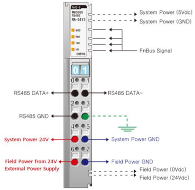
Diagram description (text version): Front view of the NA-9473 MODBUS RS-485 adapter: on top the MOD, RxD, TxD and I/O LEDs and the two rotary address switches; on the right side the FnBus contacts carrying System Power (5 Vdc and GND) and the FnBus signal to the expansion modules. The 8-pin terminal block: 0 – RS485 DATA+, 1 – RS485 DATA−, 2 – RS485 GND, 3 – shield/frame ground (FG), 4 – System Power 24 V, 5 – System Power GND, 6 – Field Power 24 V from an external supply, 7 – Field Power GND; field power (24 Vdc / 0 Vdc) is passed on to the expansion modules.
NA-9473 terminal block – pin assignment
| Pin No. | Signal Description |
|---|---|
| 0 | RS485 DATA+ |
| 1 | RS485 DATA- |
| 2 | RS485 GND |
| 3 | SHIELD/FG |
| 4 | System Power +24V |
| 5 | System Power GND |
| 6 | Field Power +24V |
| 7 | Field Power GND |
2.2 Specification
2.2.1 General Specification
General Specification
| Item | Specification |
|---|---|
| System Power | Supply voltage: 24 Vdc nominal; supply voltage range: 20~28.8 Vdc; protection: output current limit (min. 1.0 A), reverse polarity protection |
| Power Dissipation | 150 mA typical @ 24 Vdc |
| Current for I/O Module | 0.5 A @ 5 Vdc |
| Isolation | System power to internal logic: non-isolation; system power to physical (RS485) logic: non-isolation; system power to I/O driver: isolation |
| Field Power | Supply voltage: 24 Vdc nominal; supply voltage range: 11~28.8 Vdc |
| Max. Current Field Power Contact | DC 4 A max. |
| Weight | 80 g |
| Module Size | 15 mm x 99 mm x 70 mm |
| Environment Condition | Refer to Environmental Specifications |
Environmental Specifications
| Item | Specification |
|---|---|
| Operating Temperature | -20 to 55 °C |
| Non-Operating Temperature | -40 °C to 85 °C |
| Relative Humidity | 5%~90% non-condensing |
| Operating Altitude | 2000 m |
| Mounting | DIN rail |
2.2.2 Interface Specification
Interface Specification, NA-9473 (RS-485)
| Item | Specification |
|---|---|
| Adapter Type | Slave node (MODBUS Serial RTU/ASCII Server) |
| Max. Expansion Module | 12 slots |
| Max. Input Size | 64 words (128 bytes) |
| Max. Output Size | 64 words (128 bytes) |
| Max. Length Bus Line | 1200 m (NA-9473, RS-485, depends on baud rate) |
| Max. Nodes | 16 nodes (NA-9473, RS-485) |
| Baud rate | 1200, 2400, 4800, 9600, 19200, 38400, 57600, 115200 bps (SW2) |
| Protocol | RTU and ASCII |
| Settable Node Address | 1~15 with DIP switch (SW1) |
| Indicator | 4 LEDs: 1 Green/Red – Module Status (MOD); 1 Green – Received Data (RXD); 1 Green – Transmit Data (TXD); 1 Green/Red – Expansion Module Status (I/O) |
| Module Location | Starter module – left side of FnIO system |
2.3 LED Indicator
2.3.1 Module Status LED (MOD)
Module Status LED (MOD)
| State | LED is: | To indicate: |
|---|---|---|
| No Power | Off | No power is supplied to the unit. |
| Device Operational | Green | The unit is operating in normal condition. |
| Device in Standby | Flashing Green | The device needs commissioning due to configuration missing, incomplete or incorrect. |
| MODBUS Error | Green/Red Toggle | MODBUS error such as watchdog error, CRC/LRC error, setup DIP switch error, etc. |
| Minor Fault | Flashing Red | Recoverable fault – EEPROM sum check error. |
| Unrecoverable Fault | Red | The device has an unrecoverable fault – memory error or CPU watchdog error. |
2.3.2 Received Data LED (RXD)
Received Data LED (RXD)
| State | LED is: | To indicate: |
|---|---|---|
| Not Powered | Off | Device is not on-line or may not be powered. |
| Adapter received correct message frame | Flashing Green | Adapter (slave) received a correct frame addressed to the slave or broadcast. About 20 ms flashing. |
2.3.3 Transmit Data LED(TXD)
Transmit Data LED (TXD)
| State | LED is: | To indicate: |
|---|---|---|
| Not Powered | Off | Device is not on-line or may not be powered. |
| Adapter transmit frame | Flashing Green | Adapter (slave) transmits a frame. About 20 ms flashing. |
2.3.4 Expansion Module Status LED (I/O)
Expansion Module Status LED (I/O)
| State | LED is: | To indicate: |
|---|---|---|
| Not Powered / No Expansion Module | Off | Device has no expansion module or may not be powered. |
| FnBus On-line, Do not Exchanging I/O | Flashing Green | FnBus is normal but is not exchanging I/O data (passed the expansion module configuration). |
| FnBus Connection, Run Exchanging IO | Green | Exchanging I/O data. |
| FnBus connection fault during exchanging IO | Red | One or more expansion modules occurred in fault state: changed expansion module configuration; FnBus communication failure. |
| Expansion Configuration Failed | Flashing Red | Failed to initialize expansion module: detected invalid expansion module ID; overflowed input/output size; too many expansion modules; initial protocol failure; mismatch of vendor code between adapter and expansion module. |
Słowa kluczowe
NA-9473, specyfikacja, zaciski, RS-485, zasilanie 24 V, field power, temperatura pracy, diody LED, MOD, RXD, TXD, I/O, prędkość transmisji
No comments to display
No comments to display