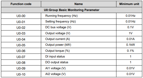
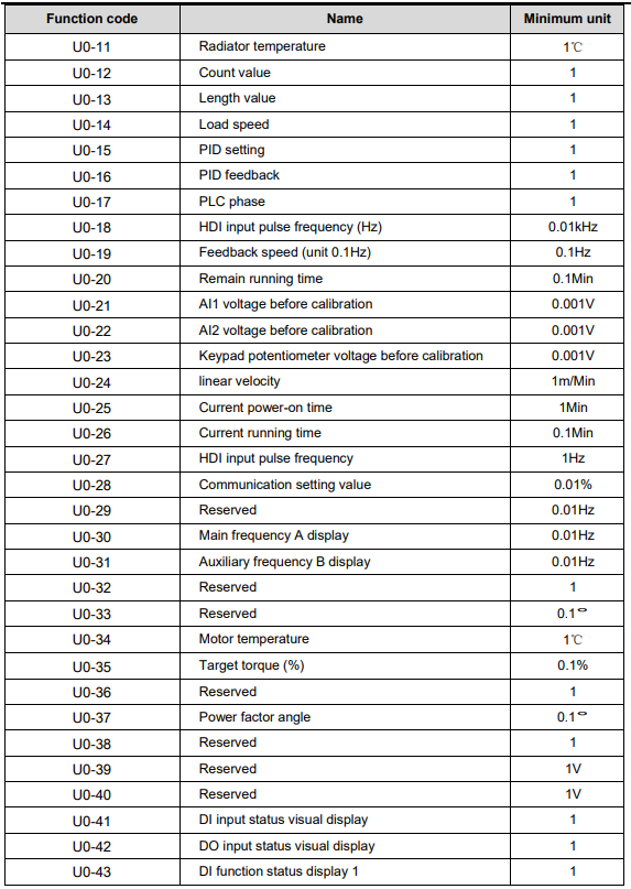
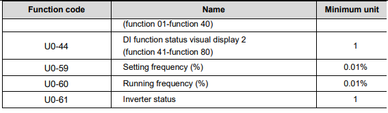
5. Function Parameter List – Part 1 (P0–P4)
Streszczenie: Tabela parametrów funkcyjnych KE300 (część 1 z 3): grupy P0–P4 (funkcje podstawowe, silnik, sterowanie wektorowe i V/F, zaciski wejściowe) – zakresy nastaw, wartości fabryczne i możliwość zmiany.
EN: KE300 function parameter list (part 1 of 3): groups P0–P4 (basic functions, motor, vector and V/F control, input terminals) – setting ranges, factory defaults and modification attributes.
Dotyczy: falownik wektorowy Micno KE300 (zasilanie 1AC/3AC 220 V, 3AC 380 V, 3AC 660 V; moce 0,4–630 kW)
Źródło: dokumentacja producenta (Micno KE300 Series Inverter User Manual); tabele przepisane z obrazów na tekst – opracowanie Multiprojekt
Nawigacja: część 1 z 3 · następna część (Part 2 (P5–P9)) →
The function parameters of KE300 series inverter have been divided into 19 groups including P0~PP, A0, U0 according to the function. Each function group contains certain function codes. For example, “P1-10” means the tenth function code in the P1 function group. P0~PE are basic function parameter groups; PF is factory parameter group (users are forbidden to access); A0 is torque control function parameter group; U0 is monitor function parameter group.
If PP-00 is set to non-zero value, it means parameter protection password is set, and the parameter menu cannot be entered until correct password is input. To cancel the password, please set PP-00 to “0”.
A0 and U0 are default hidden parameter groups, which can be displayed by modifying PP-02.
The instruction of the symbols in function parameter list is as following:“
- ○
”:– means that the parameter setting value can be modified on stop and running status.“ - ◎
”:– means that the parameter setting value cannot be modified on the running status.“ - ●
”:– means that the value of the parameter is the real detection value which cannot be modified.
5.1 Basic Function Parameter Table
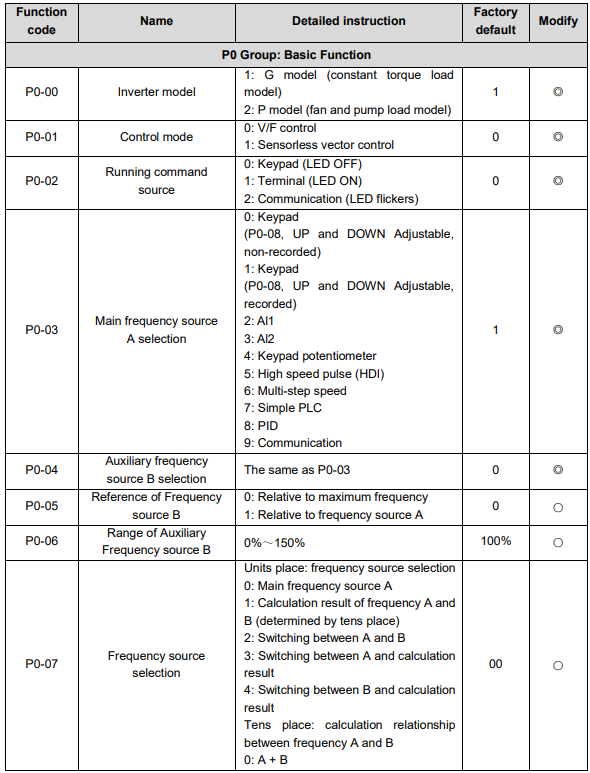
P0
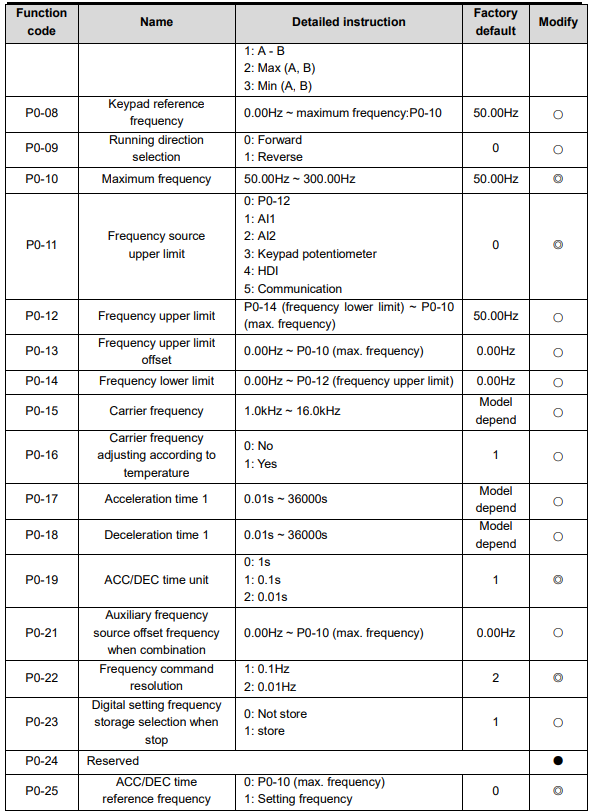
| Function
| Name | Detailed
| Factory
| Modify |
|---|---|---|---|---|
| P0-00 | Inverter
| 1:
2:
| 1 | ◎ |
| P0-01 | Control
| 0:
1:
control | 0 | ◎ |
| P0-02 | Running command source | 0: Keypad (LED OFF) 1: Terminal (LED ON) 2: Communication (LED flickers) | 0 | ◎ |
| P0-03 | Main frequency source A selection | 0: Keypad (P0-08, UP and DOWN adjustable, non-recorded) 1: Keypad (P0-08, UP and DOWN adjustable, recorded) 2: AI1 3: AI2 4: Keypad potentiometer 5: High speed pulse (HDI) 6: Multi-step speed 7: Simple PLC 8: PID 9: Communication | 1 | ◎ |
| P0-04 | Auxiliary frequency source B selection | The same as P0-03 | 0 | ◎ |
| P0-05 | Reference of frequency source B | 0: Relative to maximum frequency 1: Relative to frequency source A | 0 | ○ |
| P0-06 | Range of auxiliary frequency source B | 0% ~ 150% | 100% | ○ |
| P0-07 | Frequency source selection | Units place: frequency source selection 0: Main frequency source A 1: Calculation result of frequency A and B (determined by tens place) 2: Switching between A and B 3: Switching between A and calculation result 4: Switching between B and calculation result Tens place: calculation relationship between frequency A and B 0: A + B 1: A - B 2: Max (A, B) 3: Min (A, B) | 00 | ○ |
| P0-08 | Keypad reference frequency | 0.00Hz ~ maximum frequency: P0-10 | 50.00Hz | ○ |
| P0-09 | Running direction selection | 0: Forward 1: Reverse | 0 | ○ |
| P0-10 | Maximum frequency | 50.00Hz ~ 300.00Hz | 50.00Hz | ◎ |
| P0-11 | Frequency source upper limit | 0: P0-12 1: AI1 2: AI2 3: Keypad potentiometer 4: HDI 5: Communication | 0 | ◎ |
| P0-12 | Frequency upper limit | P0-14 (frequency lower limit) ~ P0-10 (max. frequency) | 50.00Hz | ○ |
| P0-13 | Frequency upper limit offset | 0.00Hz ~ P0-10 (max. frequency) | 0.00Hz | ○ |
| P0-14 | Frequency lower limit | 0.00Hz ~ P0-12 (frequency upper limit) | 0.00Hz | ○ |
| P0-15 | Carrier frequency | 1.0kHz ~ 16.0kHz | Model dependent | ○ |
| P0-16 | Carrier frequency adjusting according to temperature | 0: No 1: Yes | 1 | ○ |
| P0-17 | Acceleration time 1 | 0.01s ~ 36000s | Model dependent | ○ |
| P0-18 | Deceleration time 1 | 0.01s ~ 36000s | Model dependent | ○ |
| P0-19 | ACC/DEC time unit | 0: 1s 1: 0.1s 2: 0.01s | 1 | ◎ |
| P0-21 | Auxiliary frequency source offset frequency when combination | 0.00Hz ~ P0-10 (max. frequency) | 0.00Hz | ○ |
| P0-22 | Frequency command resolution | 1: 0.1Hz 2: 0.01Hz | 2 | ◎ |
| P0-23 | Digital setting frequency storage selection when stop | 0: Not store 1: Store | 1 | ○ |
| P0-24 | Reserved | – | – | ● |
| P0-25 | ACC/DEC time reference frequency | 0: P0-10 (max. frequency) 1: Setting frequency 2: 100Hz | 0 | ◎ |
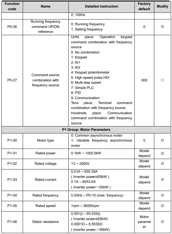
| P0-26 | Running frequency command UP/DN reference | 0: Running frequency 1: Setting frequency | 0 | ◎ |
| P0-27 | Command source combination with frequency source | Units place: operation keypad command combination with frequency source 0: No combination 1: Keypad 2: AI1 3: AI2 4: Keypad potentiometer 5: High speed pulse HDI 6: Multi-step speed 7: Simple PLC 8: PID 9: Communication Tens place: terminal command combination with frequency source Hundreds place: communication command combination with frequency source | 000 | ○ |
P1 Group: Motor Parameters
| Function code | Name | Detailed instruction | Factory default | Modify |
|---|---|---|---|---|
| P1-00 | Motor type | 0: Common asynchronous motor 1: Variable frequency asynchronous motor | 0 | ◎ |
| P1-01 | Rated power | 0.1kW ~ 1000.0kW | Model dependent | ◎ |
| P1-02 | Rated voltage | 1V ~ 2000V | Model dependent | ◎ |
| P1-03 | Rated current | 0.01A ~ 655.35A (inverter power ≤ 55kW) 0.1A ~ 6553.5A (inverter power > 55kW) | Model dependent | ◎ |
| P1-04 | Rated frequency | 0.00Hz ~ P0-10 (max. frequency) | Model dependent | ◎ |
| P1-05 | Rated speed | 1rpm ~ 36000rpm | Model dependent | ◎ |
| P1-06 | Stator resistance | 0.001Ω ~ 65.535Ω (inverter power ≤ 55kW) 0.0001Ω ~ 6.5535Ω (inverter power > 55kW) | Motor parameter | ◎ |
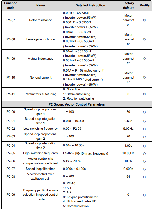
| P1-07 | Rotor resistance | 0.001Ω ~ 65.535Ω (inverter power ≤ 55kW) 0.0001Ω ~ 6.5535Ω (inverter power > 55kW) | Motor parameter | ◎ |
| P1-08 | Leakage inductance | 0.01mH ~ 655.35mH (inverter power ≤ 55kW) 0.001mH ~ 65.535mH (inverter power > 55kW) | Motor parameter | ◎ |
| P1-09 | Mutual inductance | 0.01mH ~ 655.35mH (inverter power ≤ 55kW) 0.001mH ~ 65.535mH (inverter power > 55kW) | Motor parameter | ◎ |
| P1-10 | No-load current | 0.01A ~ P1-03 (rated current) (inverter power ≤ 55kW) 0.1A ~ P1-03 (rated current) (inverter power > 55kW) | Motor parameter | ◎ |
| P1-11 | Parameters autotuning | 0: No action 1: Static autotuning 2: Rotation autotuning | 0 | ◎ |
P2 Group: Vector Control Parameters
| Function code | Name | Detailed instruction | Factory default | Modify |
|---|---|---|---|---|
| P2-00 | Speed loop proportional gain 1 | 1 ~ 100 | 30 | ○ |
| P2-01 | Speed loop integration time 1 | 0.01s ~ 10.00s | 0.50s | ○ |
| P2-02 | Low switching frequency | 0.00 ~ P2-05 | 5.00Hz | ○ |
| P2-03 | Speed loop proportional gain 2 | 1 ~ 100 | 20 | ○ |
| P2-04 | Speed loop integration time 2 | 0.01s ~ 10.00s | 1.00s | ○ |
| P2-05 | High switching frequency | P2-02 ~ P0-10 (max. frequency) | 10.00Hz | ○ |
| P2-06 | Vector control slip compensation coefficient | 50% ~ 200% | 100% | ○ |
| P2-07 | Speed loop filter time | 0.000s ~ 0.100s | 0.000s | ○ |
| P2-08 | Vector control over excitation gain | 0 ~ 200 | 64 | ○ |
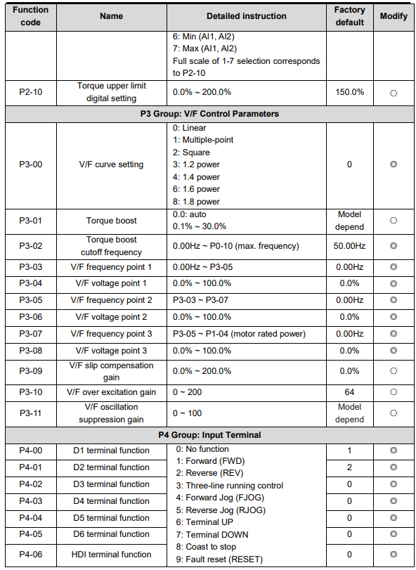
| P2-09 | Torque upper limit source selection in speed control mode | 0: P2-10 1: AI1 2: AI2 3: Keypad potentiometer 4: High speed pulse HDI 5: Communication 6: Min (AI1, AI2) 7: Max (AI1, AI2) Full scale of selections 1–7 corresponds to P2-10 | 0 | ○ |
| P2-10 | Torque upper limit digital setting | 0.0% ~ 200.0% | 150.0% | ○ |
P3 Group: V/F Control Parameters
| Function code | Name | Detailed instruction | Factory default | Modify |
|---|---|---|---|---|
| P3-00 | V/F curve setting | 0: Linear 1: Multiple-point 2: Square 3: 1.2 4: 6: 1.6 power 8: 1.8 power | 0 | ◎ |
| P3-01 | Torque boost | 0.0: auto 0.1% ~ 30.0% | Model dependent | ○ |
| P3-02 | Torque boost cutoff frequency | 0.00Hz ~ P0-10 (max. frequency) | 50.00Hz | ◎ |
| P3-03 | V/F frequency point 1 | 0.00Hz ~ P3-05 | 0.00Hz | ◎ |
| P3-04 | V/F voltage point 1 | 0.0% ~ 100.0% | 0.0% | ◎ |
| P3-05 | V/F frequency point 2 | P3-03 ~ P3-07 | 0.00Hz | ◎ |
| P3-06 | V/F voltage point 2 | 0.0% ~ 100.0% | 0.0% | ◎ |
| P3-07 | V/F frequency point 3 | P3-05 ~ P1-04 (printed in the source as “motor rated power”; P1-04 is the motor rated frequency) | 0.00Hz | ◎ |
| P3-08 | V/F voltage point 3 | 0.0% ~ 100.0% | 0.0% | ◎ |
| P3-09 | V/F slip compensation gain | 0.0% ~ 200.0% | 0.0% | ○ |
| P3-10 | V/F over excitation gain | 0 ~ 200 | 64 | ○ |
| P3-11 | V/F oscillation suppression gain | 0 ~ 100 | Model dependent | ○ |
P4 Group: Input Terminal
| Function code | Name | Detailed instruction | Factory default | Modify |
|---|---|---|---|---|
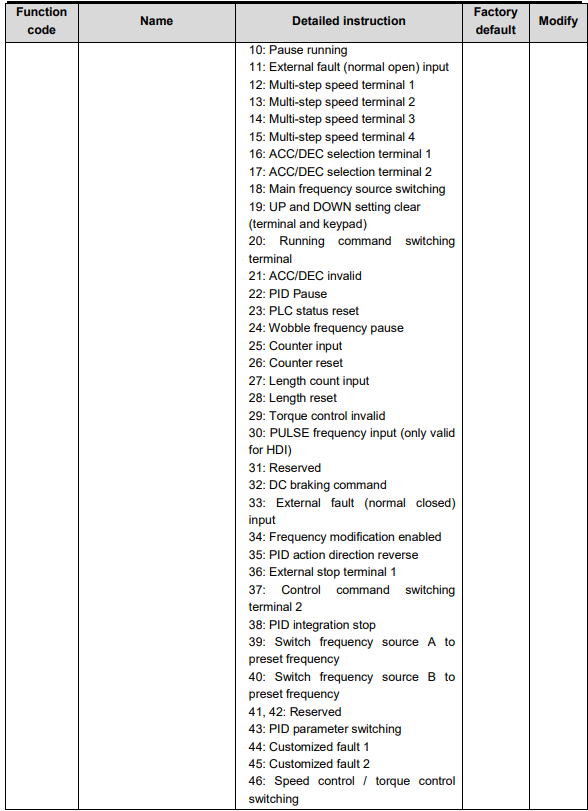
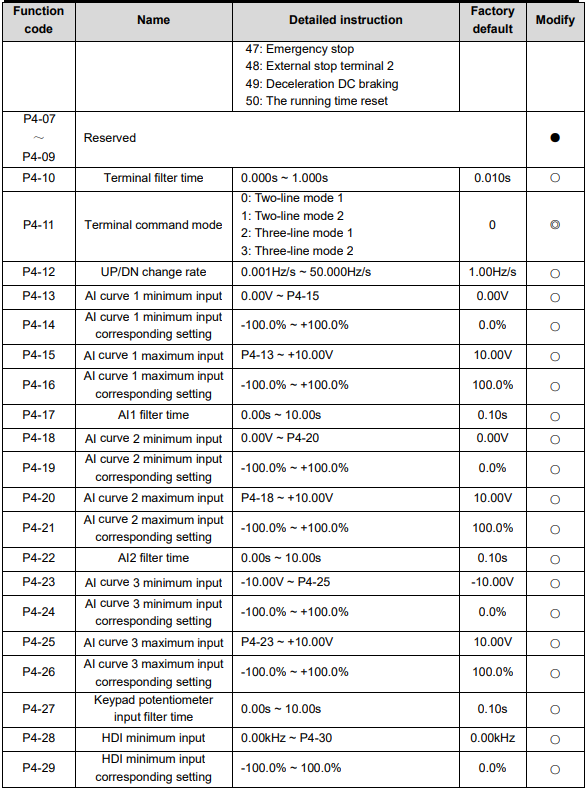
| P4-00 | D1 terminal function | 0: No function 1: Forward (FWD) 2: Reverse (REV) 3: Three-line running control 4: Forward jog (FJOG) 5: Reverse jog (RJOG) 6: Terminal UP 7: Terminal DOWN 8: Coast to stop 9: Fault reset (RESET) 10: Pause running 11: External fault (normally open) input 12: Multi-step speed terminal 1 13: Multi-step speed terminal 2 14: Multi-step speed terminal 3 15: Multi-step speed terminal 4 16: ACC/DEC selection terminal 1 17: ACC/DEC selection terminal 2 18: Main frequency source switching 19: UP and DOWN setting clear (terminal and keypad) 20: Running command switching terminal 21: ACC/DEC invalid 22: PID pause 23: PLC status reset 24: Wobble frequency pause 25: Counter input 26: Counter reset 27: Length count input 28: Length reset 29: Torque control invalid 30: PULSE frequency input (only valid for HDI) 31: Reserved 32: DC braking command 33: External fault (normally closed) input 34: Frequency modification enabled 35: PID action direction reverse 36: External stop terminal 1 37: Control command switching terminal 2 38: PID integration stop 39: Switch frequency source A to preset frequency 40: Switch frequency source B to preset frequency 41, 42: Reserved 43: PID parameter switching 44: Customized fault 1 45: Customized fault 2 46: Speed control / torque control switching 47: Emergency stop 48: External stop terminal 2 49: Deceleration DC braking 50: The running time reset | 1 | ◎ |
| P4-01 | D2 terminal function | Same as P4-00 (DI functions 0 ~ 50) | 2 | ◎ |
| P4-02 | D3 terminal function | Same as P4-00 (DI functions 0 ~ 50) | 0 | ◎ |
| P4-03 | D4 terminal function | Same as P4-00 (DI functions 0 ~ 50) | 0 | ◎ |
| P4-04 | D5 terminal function | Same as P4-00 (DI functions 0 ~ 50) | 0 | ◎ |
| P4-05 | D6 terminal function | Same as P4-00 (DI functions 0 ~ 50) | 0 | ◎ |
| P4-06 | HDI terminal function | Same as P4-00 (DI functions 0 ~ 50) | 0 | ◎ |
| P4-07 ~ P4-09 | Reserved | – | – | ● |
| P4-10 | Terminal filter time | 0.000s ~ 1.000s | 0.010s | ○ |
| P4-11 | Terminal command mode | 0: Two-line mode 1 1: Two-line mode 2 2: Three-line mode 1 3: Three-line mode 2 | 0 | ◎ |
| P4-12 | UP/DN change rate | 0.001Hz/s ~ 50.000Hz/s | 1.00Hz/s | ○ |
| P4-13 | AI curve 1 minimum input | 0.00V ~ P4-15 | 0.00V | ○ |
| P4-14 | AI curve 1 minimum input corresponding setting | -100.0% ~ +100.0% | 0.0% | ○ |
| P4-15 | AI curve 1 maximum input | P4-13 ~ +10.00V | 10.00V | ○ |
| P4-16 | AI curve 1 maximum input corresponding setting | -100.0% ~ +100.0% | 100.0% | ○ |
| P4-17 | AI1 filter time | 0.00s ~ 10.00s | 0.10s | ○ |
| P4-18 | AI curve 2 minimum input | 0.00V ~ P4-20 | 0.00V | ○ |
| P4-19 | AI curve 2 minimum input corresponding setting | -100.0% ~ +100.0% | 0.0% | ○ |
| P4-20 | AI curve 2 maximum input | P4-18 ~ +10.00V | 10.00V | ○ |
| P4-21 | AI curve 2 maximum input corresponding setting | -100.0% ~ +100.0% | 100.0% | ○ |
| P4-22 | AI2 filter time | 0.00s ~ 10.00s | 0.10s | ○ |
| P4-23 | AI curve 3 minimum input | -10.00V ~ P4-25 | -10.00V | ○ |
| P4-24 | AI curve 3 minimum input corresponding setting | -100.0% ~ +100.0% | 0.0% | ○ |
| P4-25 | AI curve 3 maximum input | P4-23 ~ +10.00V | 10.00V | ○ |
| P4-26 | AI curve 3 maximum input corresponding setting | -100.0% ~ +100.0% | 100.0% | ○ |
| P4-27 | Keypad potentiometer input filter time | 0.00s ~ 10.00s | 0.10s | ○ |
| P4-28 | HDI minimum input | 0.00kHz ~ P4-30 | 0.00kHz | ○ |
| P4-29 | HDI minimum input corresponding setting | -100.0% ~ 100.0% | 0.0% | ○ |
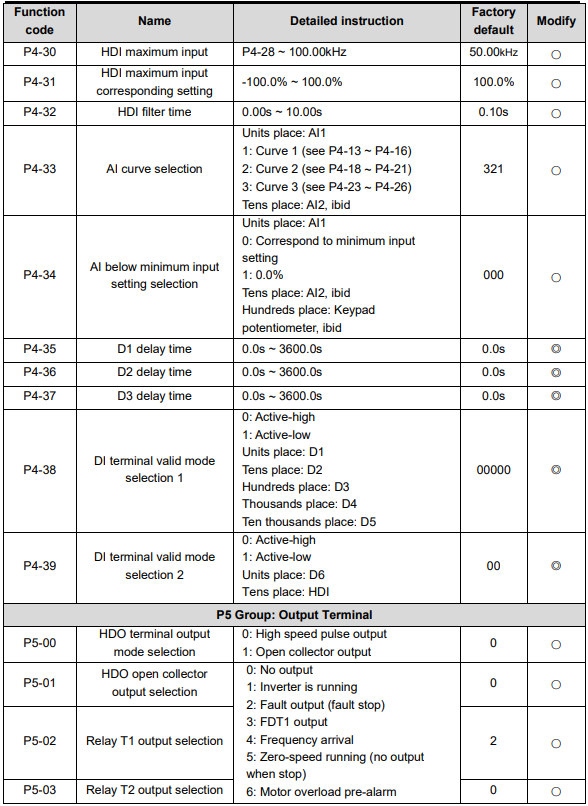
| P4-30 | HDI maximum input | P4-28 ~ 100.00kHz | 50.00kHz | ○ |
| P4-31 | HDI maximum input corresponding setting | -100.0% ~ 100.0% | 100.0% | ○ |
| P4-32 | HDI filter time | 0.00s ~ 10.00s | 0.10s | ○ |
| P4-33 | AI curve selection | Units place: AI1 1: Curve 1 (see P4-13 ~ P4-16) 2: Curve 2 (see P4-18 ~ P4-21) 3: Curve 3 (see P4-23 ~ P4-26) Tens place: AI2, ibid | 321 | ○ |
| P4-34 | AI below minimum input setting selection | Units place: AI1 0: Correspond to minimum input setting 1: 0.0% Tens place: AI2, ibid Hundreds place: keypad potentiometer, ibid | 000 | ○ |
| P4-35 | D1 delay time | 0.0s ~ 3600.0s | 0.0s | ◎ |
| P4-36 | D2 delay time | 0.0s ~ 3600.0s | 0.0s | ◎ |
| P4-37 | D3 delay time | 0.0s ~ 3600.0s | 0.0s | ◎ |
| P4-38 | DI terminal valid mode selection 1 | 0: Active-high 1: Active-low Units place: D1 Tens place: D2 Hundreds place: D3 Thousands place: D4 Ten thousands place: D5 | 00000 | ◎ |
| P4-39 | DI terminal valid mode selection 2 | 0: Active-high 1: Active-low Units place: D6 Tens place: HDI | 00 | ◎ |
Słowa kluczowe
Micno KE300, lista parametrów, parameter list, P0–P4, wartość fabryczna, factory default, zakres nastaw, setting range