9. Device Settings – Part 1 (Feature Tree, Reading Mode, Image Quality)
Streszczenie: Ustawienia ID2000 cz. 1: drzewo funkcji, tryb odczytu (dokładny/wsadowy), parametry obrazu, polling (single/multiple), oświetlenie i celownik, Smart Tune, ostrość (auto, ręczna, ROI), samoczynne dopasowanie i obraz testowy.
EN: ID2000 settings part 1: feature tree, code reading mode (accurate/batch), image parameters, polling, light source and aiming, smart tune, focus (auto, manual, ROI), self-adaptive adjustment and test pattern.
Dotyczy: przemysłowy czytnik kodów Hikrobot serii ID2000 (typy I–VII; Fast Ethernet, USB lub RS-232; obsługa przez klienta IDMVS i kody konfiguracyjne)
Źródło: dokumentacja producenta (Hikrobot ID2000 Series Industrial Code Reader User Manual); tabele i uwagi przepisane z obrazów na tekst; opisy rysunków – opracowanie Multiprojekt
Rozdział 9 „Device Settings” – części: Part 1 – Feature Tree, Reading Mode, Image Quality | Part 2 – Code Algorithm and Line Mode | Part 3 – Signal Input and Output | Part 4 – Communication and Data Processing | Part 5 – Multicast, Contrast, Statistics, Events, User Set
następna część →
9.1 Feature Tree Introduction
After the device is connected to the client software, and you can right click the device in Device Connection, and click Feature Tree.
Note: The parameters of the feature tree may differ by device models and firmware versions.
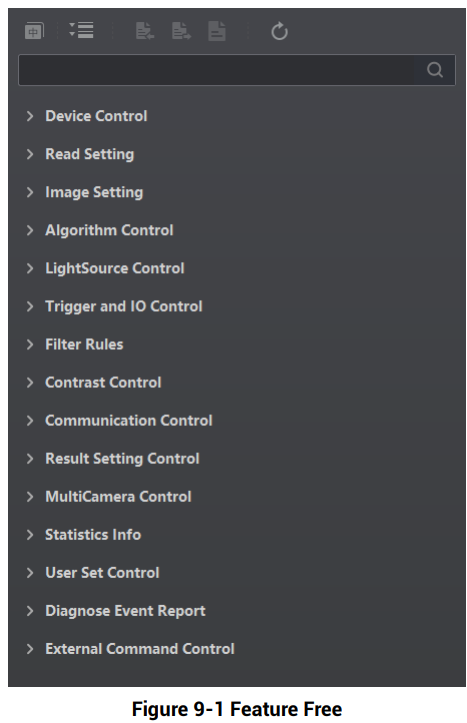
Figure 9-1 Feature Tree
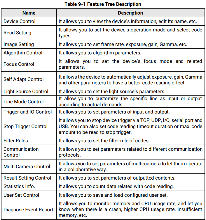
Table 9-1 Feature Tree Description
| Name | Description |
|---|---|
| Device Control | It allows you to view the device’s information, edit its name, etc. |
| Read Setting | It allows you to set the device’s operation mode and select code types. |
| Image Setting | It allows you to set frame rate, exposure, gain, Gamma, etc. |
| Algorithm Control | It allows you to set algorithm parameters. |
| Focus Control | It allows you to set the device’s focus mode and related parameters. |
| Self Adapt Control | It allows the device to automatically adjust exposure, gain, Gamma and other parameters to have a better code reading effect. |
| Light Source Control | It allows you to set the light source’s parameters. |
| Line Mode Control | It allows you to customize the specific line as input or output according to actual demands. |
| Trigger and IO Control | It allows you to set parameters of input and output. |
| Stop Trigger Control | It allows you to stop device trigger via TCP, UDP, I/O, serial port and USB. You can also set the code reading timeout duration or the max. code amount to be read to stop trigger. |
| Filter Rules | It allows you to set the filter rule of codes. |
| Communication Control | It allows you to set parameters related to different communication protocols. |
| Multi Camera Control | It allows you to set parameters of multi-camera to let them operate in a collaborative way. |
| Result Setting Control | It allows you to set parameters of outputted contents. |
| Statistics Info. | It allows you to count data related to code reading. |
| User Set Control | It allows you to save and load configured user sets. |
| Diagnose Event Report | It allows you to monitor memory and CPU usage rate, and lets you know when there is a crash, higher CPU usage rate, insufficient memory, etc. |
9.2 Code Reading Mode Settings
The device supports different code reading modes, including accurate mode and batch mode.
Steps1.
- Right click the device in Device Connection, and click Feature Tree.
2. - Go to Trigger and IO Control → Accurate Mode Enable, and enable Accurate Mode Enable.

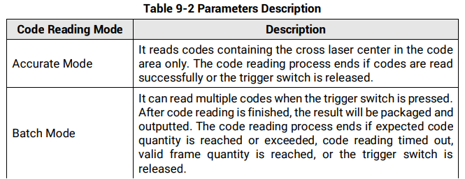

Table 9-2 Parameters Description
| Code Reading Mode | Description |
|---|---|
| Accurate Mode | It reads codes containing the cross laser center in the code area only. The code reading process ends if codes are read successfully or the trigger switch is released. |
| Batch Mode | It can read multiple codes when the trigger switch is pressed. After code reading is finished, the result will be packaged and outputted. The code reading process ends if the expected code quantity is reached or exceeded, code reading timed out, the valid frame quantity is reached, or the trigger switch is released. |
Note: The function of code reading mode may differ by device models.
9.3 Image Quality Settings
This section introduces how to set image related parameters of the device via client software.

9.3.1 Set Image
You can set parameters like exposure time, gain, Gamma, acquisition frame rate, acquisition burst frame count, etc. in Image Settings area.
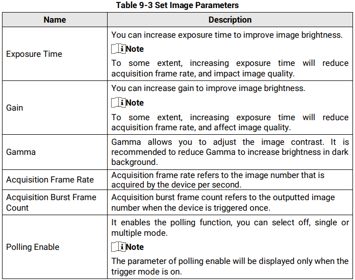
| Name | Description |
|---|---|
| Exposure Time | You can increase exposure time to improve image brightness. Note: To some extent, increasing exposure time will reduce acquisition frame rate, and impact image quality. |
| Gain | You can increase gain to improve image brightness. Note (as in the source): To some extent, increasing exposure time will reduce acquisition frame rate, and affect image quality. |
| Gamma | Gamma allows you to adjust the image contrast. It is recommended to reduce Gamma to increase brightness in dark background. |
| Acquisition Frame Rate | Acquisition frame rate refers to the image number that is acquired by the device per second. |
| Acquisition Burst Frame Count | Acquisition burst frame count refers to the outputted image number when the device is triggered once. |
| Polling Enable | It enables the polling function; you can select off, single or multiple mode. Note: The parameter of polling enable will be displayed only when the trigger mode is on. |
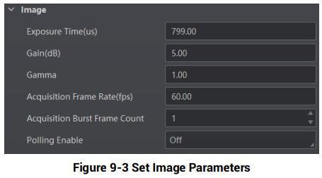
Figure 9-3 Set Image Parameters
Figure description (text version): Image parameter group: Exposure Time (us) 799.00, Gain (dB) 5.00, Gamma 1.00, Acquisition Frame Rate (fps) 60.00, Acquisition Burst Frame Count 1, Polling Enable Off.
9.3.2 Set Polling
The polling function allows the device to acquire images based on the parameters you set, including exposure time, gain, Gamma, light source, focus position, etc. Currently, two types of polling modes are available, including single mode and multiple mode.
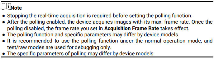
- Stopping the real-time acquisition is required before setting the polling function.
- After polling is enabled, the device acquires images with its max. frame rate. Once polling is disabled, the frame rate you set in Acquisition Frame Rate takes effect.
- The polling function and specific parameters may differ by device models.
- It is recommended to use the polling function in the normal operation mode; test/raw modes are used for debugging only.
- The specific parameters of polling may differ by device models.
Single Mode
Single Mode
Steps1.
- Right click the device in Device Connection, and click Feature Tree.
2. - Go to Image Setting → Polling Mode, and select Single as Polling Enable.
3. - Select one parameter (e.g. Param1) from Polling Param.
Note: Up to 8 sets of parameters can be selected from Polling Param.

4.
- Set parameters participating the polling like Polling Exposure Time, Polling Gain, Polling Gamma, etc. according to actual demands.
Table 9-4 Parameters of Single Mode Polling
| Parameter | Description |
|---|---|
| Polling Exposure Time | It sets the exposure time of polling. |
| Polling Gain | It sets the polling gain. |
| Polling Gamma | It sets the polling Gamma value. • If the value is between 0 and 1, the image brightness increases and the dark area becomes brighter. • If the value is between 1 and 4, the image brightness decreases and the dark area becomes darker. |
| Polling Focus Enable | After enabling this parameter, you can set the polling focus position. |
| Polling Focus Position | It sets the polling focus position. |
| Polling Lighting Selector | It selects lamps in different directions, including up/down and mid. |
| Polling Lighting Enable | After enabling this parameter, the light source will turn on. |
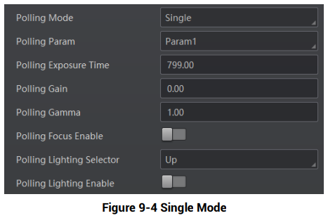
Figure 9-4 Single Mode

Multiple
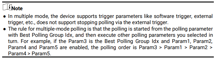
ModeMultipleNote:
- In
Mode
multiple
Steps1.
- Right click the device in Device Connection, and click Feature Tree.
2. - Go to Image Setting → Polling Mode, and select Multiple as Polling Enable.
3. - Set Polling Time and Polling Period according to actual demands.
●- Polling Time is used to determine whether the polling is finished or not, and it ranges from 100 to 2147482.
● - Polling Period is whole period from Param1 to Param8, and it ranges from 1 to 5000.
4.
- Polling Time is used to determine whether the polling is finished or not, and it ranges from 100 to 2147482.
- Select 2 to 8 sets of parameters (e.g. Param1 and Param2) from Polling Param, and enable Polling Param Enable to let them take effect.
5. - Set parameters participating the polling like Polling Exposure Time, Polling Gain, Polling Gamma, etc. according to actual demands.
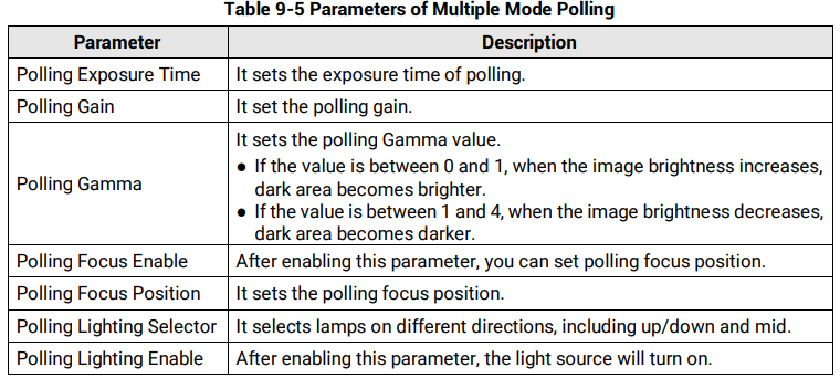
| Parameter | Description |
|---|---|
| Polling
| It sets the exposure time of polling. |
| Polling Gain | It sets the polling gain. |
| Polling Gamma | It sets the polling Gamma value. • If the value is between 0 and 1, the image brightness increases and the dark area becomes brighter. • If the value is between 1 and 4, the image brightness decreases and the dark area becomes darker. |
| Polling Focus Enable | After enabling this parameter, you can set the polling focus position. |
| Polling Focus Position | It sets the polling focus position. |
| Polling Lighting Selector | It selects lamps in different directions, including up/down and mid. |
| Polling Lighting Enable | After enabling this parameter, the light source will turn on. |
- Repeat step 4 and step 5 to set other parameters from Polling Param.
7. - (Optional) View Polling Status and Best Polling Group Idx.
●- Polling Status: It displays the current polling status. 0 stands for polling ended, and 1 stands for polling started.
● - Best Polling Group Idx: It is used to display the polling parameter number when the device recognizes codes after enabling polling. If the polling is disabled or polling parameters are edited, it displays 1 by default.
- Polling Status: It displays the current polling status. 0 stands for polling ended, and 1 stands for polling started.
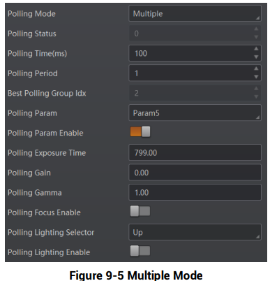
Figure 9-5 Multiple Mode
Figure description (text version): Polling parameters in multiple mode: Polling Mode Multiple, Polling Status 0, Polling Time (ms) 100, Polling Period 1, Best Polling Group Idx 1, Polling Param Param1, Polling Param Enable on, Polling Exposure Time 799.00, Polling Gain 0.00, Polling Gamma 1.00, Polling Focus Enable off, Polling Lighting Selector Up, Polling Lighting Enable off.
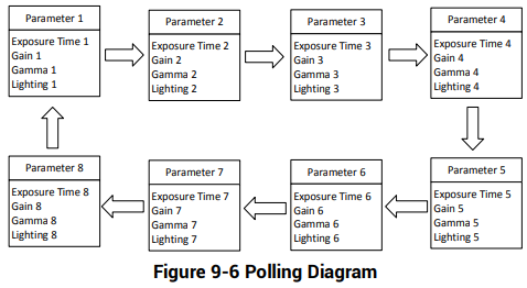
Figure 9-6 Polling Diagram
9.3.3 Set Light Source
Light source control allows you to enable the device’s aiming system and light source, and set related parameters according to actual demands.

- Light
source parameters may differ by device models.
- Make sure you have selected the device to be set in Device Connection before setting light source parameters.
Type I Device to Type VI Device
Steps1.
- Go to Image Settings → Light, and enable Aiming Light Enable according to actual demands.
2. - Enable Lighting Enable to enable the light source according to actual demands.
3. - (Optional) Set Lighting Duration and Precharge Time if Lighting Enable is enabled.
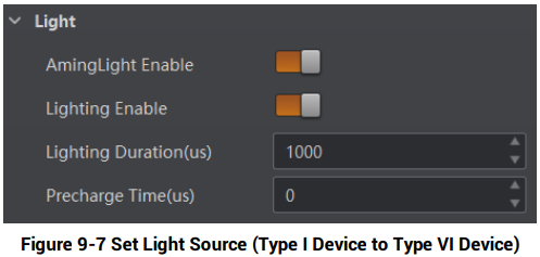
Figure 9-7 Set Light Source (Type I Device to Type VI Device)
Figure description (text version): Light group: AimingLight Enable on, Lighting Enable on, Lighting Duration (us) 1000, Precharge Time (us) 0.
Type VII Device
Steps1.
- Go to Image Settings → Light, and select Lighting Mode according to actual demands.
2. - Enable Laser Enable according to actual demands.
3. - Enable Laser Delay Enable, and enter Laser Delay Duration to delay the close time of the laser after the device stops triggering.
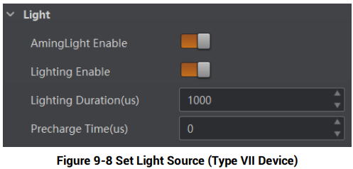
Figure 9-8 Set Light Source (Type VII Device)
Figure description (text version): Light group as shown in the source: AimingLight Enable on, Lighting Enable on, Lighting Duration (us) 1000, Precharge Time (us) 0 (the screenshot is the same as in Figure 9-7).
9.3.4 Set Smart Tune
The smart tune function allows you to adjust the device’s focus position, exposure, gain, etc. by one-key operation, and supports self-adaptive adjustment.
The smart tune function has two methods to be realized, including smart tune by pressing tune button and smart tune via the client software.
Smart Tune by Pressing Tune Button
Note:
- The
parameters of the smart tune may differ by device models and firmware versions.
- During the smart tune process, the focus parameters and self-adaptive parameters will be adjusted in turn.

Steps1.
- Go to Image Settings, click All Features on the right corner, and find Smart Tune Control.
2. - Enable Button Tune, and disconnect the device from the client software.
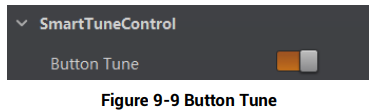
Figure 9-9 Button Tune
Figure description (text version): SmartTuneControl group with the Button Tune switch turned on.

3.
Smart Tune via Client Software
Apart from pressing tune button to realize smart tune, you can also configure parameters via the client software to realize it.
Before You Start: Make sure that the device is not in trigger mode, and its operation mode is test.
Steps1.
- Go to Image Settings, click All Features on the right corner, and find Smart Tune Control.
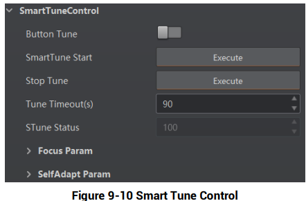
Figure 9-10 Smart Tune Control
2.Figure description (text version): SmartTuneControl group: Button Tune off, SmartTune Start (Execute), Stop Tune (Execute), Tune Timeout (s) 90, STune Status 100 (read-only), and the collapsed sub-groups Focus Param and SelfAdapt Param.
- (Optional) Set Tune Timeout. If the self-adaptive adjustment exceeds configured value, and it will stop automatically.
3. - Click Execute in Smart Tune Start to let the device start smart tune, and a window of smart tune will be displayed for you to view the effect.
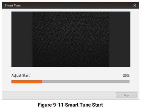
Figure 9-11 Smart Tune Start
Figure description (text version): Smart Tune window: image preview area, status "Adjust Start" with progress 26% and an orange progress bar, Stop button at the bottom right.
4.
- (Optional) View smart tune process via Smart Tune Status.
5. - Click Execute in Stop Tune to stop smart tune process.
9.3.5 Set Focus
The device supports the focus function according to the code position in the field of view. Currently, three types of focus are supported, including global auto focus, global manual focus, and ROI focus.

Note:
- Make sure that the device’s operation mode is test before performing focus, and switch to the normal operation mode after the focus is completed.
- The focus function may differ by device models.
Global Auto Focus
The global auto focus allows you to adjust lens focus in a global field of view just by once.
Steps1.
- Go to Image Settings → Smart Tune Control → Focus Param → Focus Mode Selector, and select Whole Area Focus as Focus Mode Selector.
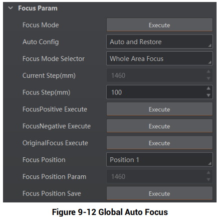
Figure 9-12 Global Auto Focus
2.Figure description (text version): Focus Param group: Focus Mode (Execute), Auto Config Auto and Restore, Focus Mode Selector Whole Area Focus, Current Step (mm) 1900 (read-only), Focus Step (mm) 100, FocusPositive Execute, FocusNegative Execute, OriginalFocus Execute (Execute buttons), Focus Position Position 1, Focus Position Param 1900, Focus Position Save (Execute).
- Click
 in the live view window, and click it again to stop acquisition and make sure there is an image in the window.
3. - Select the focus mode in Auto Config:
●- Full Auto: In this mode, the device will automatically change parameters like focus position, exposure, gain, Gamma and light source when adjusting focus.
● - Motor Only: In this mode, the device will change focus position only when adjusting focus.
● - Auto and Restore: In this mode, the device will automatically change parameters like focus position, exposure, gain, Gamma and light source when adjusting focus, and keep focus position and restore other parameters after completing focus adjustment.
4.
- Full Auto: In this mode, the device will automatically change parameters like focus position, exposure, gain, Gamma and light source when adjusting focus.
- Click Execute in Focus Mode, and the device starts to adjust focus automatically.


5.
- (Optional) Select the position parameter from Focus Position, and click Execute in Focus Position Save to save the focus position after adjusting focus.
Global Manual Focus
The global manual focus requires manual focus according to the images displayed in the live view window.
Steps1.
- Go to Image Settings → Smart Tune Control → Focus Param → Focus Mode Selector, and select Whole Area Focus as Focus Mode Selector.
2. - Click
Click in the live view window, and click it again to stop acquisition and make sure there is an image in the window.3. - Select Focus Position according to actual demands and Focus Position Param.
4. - Set Focus Step according to actual demands.
5. - Click Execute in Focus Positive Execute and Focus Negative Execute to adjust focus position.
6. - (Optional) View Focus Score to know the score of the focus adjustment.
7. - (Optional) Select the position parameter from Focus Position, and click Execute in Focus Position Save to save the focus position after adjusting focus.
8. - (Optional) Click Execute in Original Focus Execute to let the focus back to its original position.
ROI Focus
The ROI focus allows you to adjust lens focus regarding the ROI area by drawing specific area.

Steps1.
- Go to Image Settings → Smart Tune Control → Focus Param → Focus Mode Selector, and select ROI Area Focus as Focus Mode Selector.
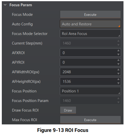
Figure 9-13 ROI Focus
2.Figure description (text version): Focus Param group: Focus Mode (Execute), Auto Config Auto and Restore, Focus Mode Selector ROI Area Focus, Current Step (mm) 1900, AFXROI 0, AFYROI 0, AFWidthROI (px) 2048, AFHeightROI (px) 1536, Focus Position Position 1, Focus Position Param 1900, Draw Focus ROI (Draw), Max Focus ROI (Execute).
- Click
 in the live view window, and click it again to stop acquisition and make sure there is image in the window.
3. - Click Draw in Draw Focus ROI, and draw ROI by dragging the mouse in live view window.

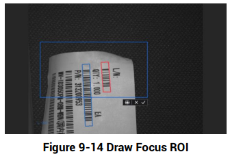
Figure 9-14 Draw Focus ROI
Figure description (text version): Live view image of a label with several codes; a blue rectangular focus ROI is drawn over part of the label.
4.
- (Optional) Set following parameters to adjust ROI size and position.
●- AF Offsex X: It is X coordinate of the upper left corner in ROI where executes auto focus.
● - AF Offsex Y: It is Y coordinate of the upper left corner in ROI where executes auto focus.
● - AF Width ROI: It refers to the width in ROI where executes auto focus.
● - AF Height ROI: It refers to the height in ROI where executes auto focus.
5.
- AF Offsex X: It is X coordinate of the upper left corner in ROI where executes auto focus.
- (Optional) Click Execute in Max. Focus ROI to have a global focus.
6. - (Optional) Repeat step 3 if you want to set multiple ROIs.
9.3.6 Set Self-Adaptive Adjustment
The function of self-adaptive adjustment can automatically adjust exposure, gain, Gamma and other parameters to have a better code reading effect.

Steps1.
- Go to Image Settings → Smart Tune Control → Self Adapt Adjust, and unfold Self Adapt Adjust.
2. - Select Adjust Source according to actual demands.
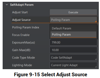
Figure 9-15 Select Adjust Source
●Figure description (text version): SelfAdapt Param group: Adjust Start (Execute), Adjust Source drop-down opened with Default Param and Polling Param, Polling Param Index, Focus Enable, ExposureMax (us) 799.00, Gain Max (dB) 10.00, Code Type Mode Code SelfAdapt, Lighting Mode Current Light Adapt.
- Default Param: It adjusts the default parameters.
● - Polling Param: It adjusts parameters configured in polling. After Polling Param is selected as Adjust Source, you should select a polling parameter group from Polling Param and enable or disable Focus Enable.
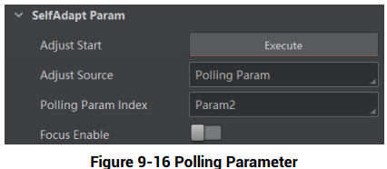
Figure 9-16 Polling Parameter
3.Figure description (text version): SelfAdapt Param group: Adjust Start (Execute), Adjust Source Polling Param, Polling Param Index Param2, Focus Enable off.
- Set Exposure Max or Gain Max according to actual demands.
●- Exposure Max: It sets the max. exposure during the self-adaptive adjustment.
● - Gain Max: It sets the max. gain during the self-adaptive adjustment.
4.
- Exposure Max: It sets the max. exposure during the self-adaptive adjustment.
- (Optional) Set self-adaptive code type in Code Type Mode.
●- Code Self-Adaptive: All code types added in field of view will be self-adaptive.
● - 1D Code: 1D code types added in field of view will be self-adaptive.
● - 2D Code: 2D code types added in field of view will be self-adaptive.
● - Stacked Code: Stacked code types added in field of view will be self-adaptive.
5.
- Code Self-Adaptive: All code types added in field of view will be self-adaptive.
- (Optional) Set light source parameters in Lighting Mode.
●- Light Adapt: The client software will select the best one from all lighting options during the self-adaptive adjustment.
● - Current Light Adapt: The client software will use the current configured light source.
● - All Light Disable: All light sources will be turned off during self-adaptive adjustment process.
6.
- Light Adapt: The client software will select the best one from all lighting options during the self-adaptive adjustment.
- Click Execute in Adjust Start. The device will automatically acquire images and perform self-adaptive adjustment, and stop acquisition after adjustment is completed.


Note: If the adjustment is completed, the client software displays the spent time and prompts that the adjustment succeeded. If the adjustment failed or timed out, the client software prompts adjustment failure or timeout.
9.3.7 Set Test Pattern
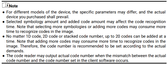
Test pattern helps troubleshooting image problems and images in the test pattern are only for test. When exceptions occur in images acquired by the device in real time, you can check if images in the test pattern have similar problems to determine the cause of an exception.

- The test pattern is available in the test or raw operation mode.
- Specific parameters of this function may differ by device models.
Go to Image Settings, click All Features, find Test Pattern in Other Features, and set Test Pattern according to actual demands.
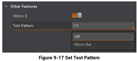
Figure
9-17 Set Test Pattern
9.4Figure Codedescription Algorithm(text Settingsversion):The codeOther readerFeatures supportsgroup: readingMirror multipleX typesswitched ofon, 1DTest code,Pattern 2Ddrop-down code,opened with the options Off (selected) and stackedMono codes, and you can add and set code parameters via the client software.
Bar.
Słowa kluczowe
9.4.1Hikrobot AddID2000, CodeAddingfeature codetree, beforeaccurate youmode, setbatch codemode, parameters via the client software. In Algorithm Settings, you can add different types of codes according to actual demands.In Algorithm Settings, click Add Barcode, select types of codes to be read, and set the 1D Code Number, 2D Code Number, and Stack Bar Number according to actual demands
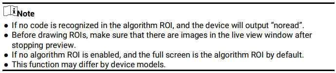
9.4.2 Set Code Reading ROIAlgorithm ROI (Region of Interest) allows the device to execute algorithms and read codes on the specific area you selected, and thus improving code reading efficiency.Currently, multiple ROIs can be configured, and the device outputs codes according to the number of ROI (e.g. Region 1, Region 2, and Region 3…) in turn. The client software supports drawing single group of ROI and drawing ROI via chessboard.
Draw Single Group of ROISteps1. Go to Algorithm Settings, and find Algorithm ROI.2. Click Draw in Draw ROI to draw ROI in the live view window.
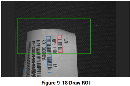
3. (Optional) Repeat the above step to draw multiple ROIs according to actual demands.

4. (Optional) Set other ROI parameters according to actual demands.● ROI Index: It indicates different ROIs and ranges from 0 to 149 corresponds 1 to 150 ROIs.● Algo Region Left X: It refers to the X coordinate of the upper left corner in algorithm ROI.● Algo Region Left Y: It refers to the Y coordinate of the upper left corner in algorithm ROI.● Algo Region Width: It refers to the width in algorithm ROI.● Algo Region Height: It refers to the height in algorithm ROI.5. (Optional) Click Execute in Restore Max. Algorithm ROI to restore the ROI to the full screen.6. (Optional) Click Execute in Clear All ROI to delete all ROIs.
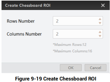
Draw ROI via ChessboardSteps1. Go to Algorithm Settings, and find Algorithm ROI.2. Click Execute in Chessboard ROI, set parameters, and click OK after setting.
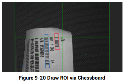
3. Click after creating ROI, and the red frame becomes green as shown below.
4. (Optional) Click 
to restore the ROI to full screen, and click 
to clean all ROIs.5. Repeat other optional steps mentioned in drawing single group of ROI.

9.4.3 Set Algorithm Parameter
In Algorithm Parameter, select 1DCode, 2DCode or Stacked Code as Arithmetic Type, and then you can set its corresponding parameters.

Set 1D Code● Timeout Value: Timeout value refers to the maximum running time of algorithm, and its unit is ms. The code reader will stop parsing the images and return results if the time is exceeded the waiting time configured.● Code Color: It defines the readable code color. White Code On Black Wall means that the client software can recognize the white code with black background. Black Code On White Wall means that the client software can recognize the black code with white background. Adaptive means that the client software can recognize both the black code with white background, and the white code with black background.● Code 39 Check: Enable this parameter if Code 39 uses the parity bit.

● ITF 25 Check: Enable this parameter if ITF 25 uses the parity bit

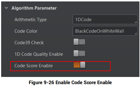
● 1D Code Quality Enable: If it is enabled, the client software will judge the quality of 1D code and output overall grade. Currently, this parameter is only applicable to Code 39 and Code 128.● Code Score Enable: If it is enabled, the client software will evaluate the code reading environment for 1D code and output code score.
Set 2D Code● Timeout Value: Timeout value refers to the maximum running time of algorithm, and its unit is ms. The code reader will stop parsing the images and return results if the time is exceeded the waiting time configured.● Algorithm Running Mode: It is used to be set the algorithm operating mode. It includes High Speed, High Performance, and Balance. High Speed focuses on recognition speed, and the algorithm can recognize the code rapidly, while High Performance refers to the algorithm can recognize the code that has distortion, spot or white gap, but its recognition speed is slow. Balance refers to the algorithm makes a balance between speed and performance.● 2D Code Max. Size: It refers to the max. recognizable code width. The 2D code will not be recognized if its width exceeds the configured value.● Mirror Mode: It is useful when the recognized image is a mirror one, mirroring in X coordinate. 3 modes are available: Adaptive, Mirror, and Non Mirror.● Downsampling Level: It refers to the pixel sample size that the code reader takes. Increasing this parameter will improve the code reading efficiency at the expense of code recognition rate.

● Code Color: It defines the readable code color. Adaptive means that the client software can recognize both the black code with white background, and the white code with black background. White Code On Black Wall means that the client software can recognize the white code with black background. Black Code On White Wall means that the client software can recognize the black code with white background.
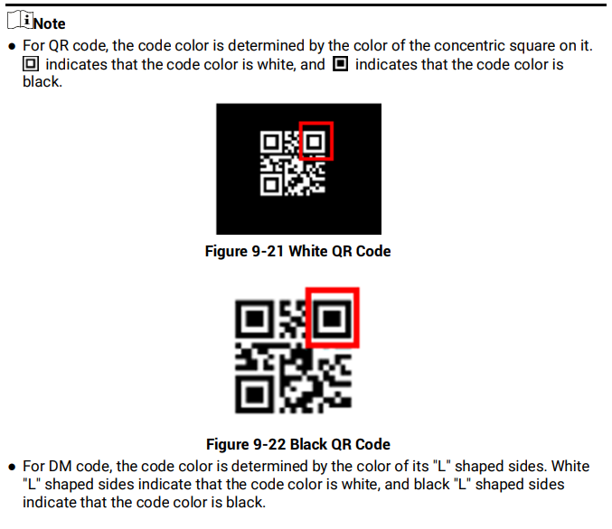
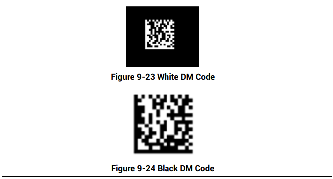
● Discrete Flag: Continuous stands for the minimum units in the "L" shaped sides of the DM code are continuous, or the minimum units in the concentric square like 
or 
in the QR code are continuous. Usually the continuous code uses squares as the minimum units. Discrete stands for the minimum units in the "L" shaped sides of the DM code are discrete, or the minimum units in the concentric square like or in the QR code are discrete. Usually the discrete code uses dots as the minimum units.Adaptive stands for the device can recognize both continuous code and the discrete code.● QR Distortion Correction: If the QR code or DM code is distorted, you can enable this parameter to improve code recognition rate.

● DM Code Shape: It defines the recognizable code shape. Square stands for square mode:If the 2D code is square shaped, it can be recognized by the device. Rectangle stands for rectangle mode: If the 2D code is rectangle shaped, it can be recognized by the device.Adaptive stands for compatible mode: The device can recognize 2D codes of both the above-mentioned two shapes.● DM Code Type: It includes All, ECC140, and ECC200.● 2D Code Quality Enable: Refer to section Set 2D Code Quality Evaluation for details.● Code Score Enable: If it is enabled, the device will evaluate code quality and display overall grade and code score in history record area of the client software. The higher the score, and the better the code quality.● Accurate Timeout Enable: If it is enabled, the accuracy of algorithm timeout will improve.
Set Stacked CodeCode Score Enable: If it is enabled, the client software will evaluate the code reading environment for stacked code and output code score.
9.4.4 Set Code Quality EvaluationThe code quality evaluation function judges the quality of codes and outputs overall grade. Currently, only 1D code and 2D code support code quality evaluation.

Set 1D Code Quality EvaluationThe 1D quality evaluation function uses the ISO15416 standard to judges the quality of codes and outputs overall grade. Currently, this function is only applicable to Code 39 and Code 128.Steps1. Go to Algorithm Control → Algorithm Parameter, and select 1D Code as Arithmetic Type.2. Enable 1D Code Quality Evaluation.3. Enable different quality evaluation standards according to actual demands.
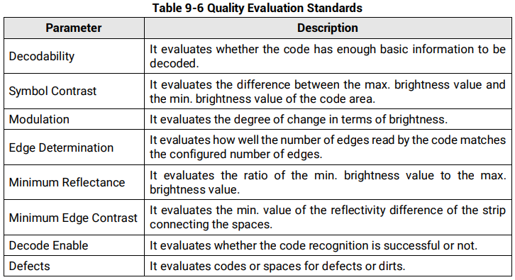

4. Set the evaluation value for A/B/C/D grade according to actual demands.
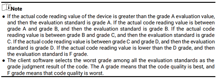
5. Enable Aperture Enable and enter Aperture according to the smallest size of codes.6. (Optional) Set Quality 1D Max Num to configure the amount of code to be evaluated. If the actual amount of code exceeds the configured, the later codes will not be evaluated.7. (Optional) Go to Algorithm Control → Rating Standard 1D Enable, set enable Rating Standard 1D Enable, and select 1D Rating Standard.

7. Click 
to start acquisition, and the client software will display the overall code quality in the history record area.
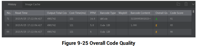
Set 2D Code Quality EvaluationThe 2D quality evaluation function uses the ISO15415 standard to judges the quality of codes and outputs overall grade.

Steps1. Go to Algorithm Control → Algorithm Parameter, and select 2D Code as Arithmetic Type.2. Enable 2D Code Quality Evaluation.3. Set Iso Edition, including Iso15415 and Iso29158● Iso15415 is applicable to the quality evaluation for label 2-dimensional codes.● Iso29158 is applicable to the quality evaluation for DPM format 2-dimensional codes.4. Refer to step 5 to step 7 in Set 1D Code Quality Evaluation to set other parameters.
9.4.5 Set Code ScoreThe code score function evaluates the code-reading environment for codes and outputs code score.
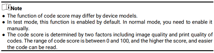
Steps1. Go to Algorithm Settings, and enable Code Score Enable.
2. Click 
to start acquisition, and the client software will display specific code score in the history record area.
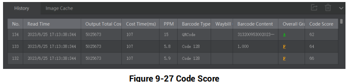
3. (Optional) Go to Image Settings, and adjust parameters like exposure time,exposure, gain, Gamma, polling, light source, etc. if the code score is low.

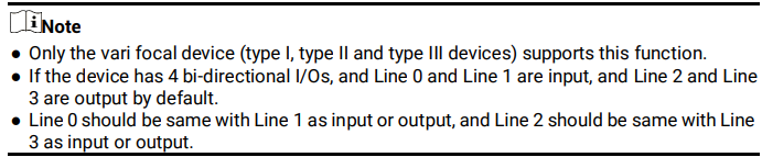
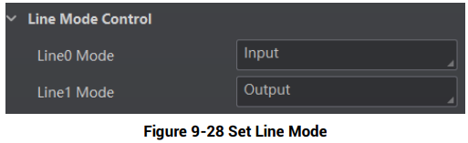
9.5 Line Mode SettingsLine mode settings allow you to customize the specific line as input or output according to actual demands.Go to I/O Control Settings → Line Mode Control, and set Input or Output according to actual demands.
9.6 Signal Input Settings
In the signal input module, you can set the trigger related parameters. You can enable trigger mode to let the acquisition of image data occur only when the trigger source is generated.
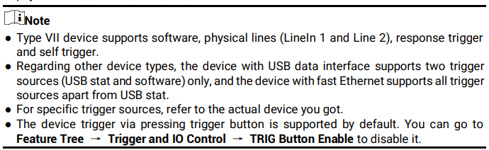
9.6.1 Set Trigger ModeThe device has 2 types of trigger mode: Internal trigger mode and external trigger mode.● Internal Trigger Mode: The device acquires images via its internal signals.● External Trigger Mode: The device acquires images via external signals like software signal and hardware signal. The trigger source of external trigger mode includes software, physical lines, counter, TCP, UDP, etc.
9.6.2 Enable Internal Trigger ModeIn the internal trigger mode, the device acquires images via its internal signals. You have 2 methods to enable the internal trigger mode:● Click I/O Control Settings → Input → Trigger Mode, and select Off as Trigger Mode.● In the live view page, click 
to enable the internal trigger mode.
9.6.3 Enable External Trigger ModeIn the external trigger mode, the device acquires images via external signals like software signal and hardware signal. You have 2 methods to enable the external trigger mode:● Click I/O Control Settings → Input → Trigger Mode, and select On as Trigger Mode.● In the live view page, click 
to enable the external trigger mode.
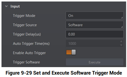
Set and Execute Software Trigger ModeIn software trigger, the software sends trigger signal to the device via I/O interface to acquire images.
Steps1. Click I/O Control Settings → Input → Trigger Mode.2. Select On as Trigger Mode.3. Select Software as Trigger Source.4. Click Execute in Trigger Source to send trigger commands.You can also enter Auto Trigger Time, and then enable Enable Auto Trigger to let the client software automatically send trigger signal to device according to the interval you set.
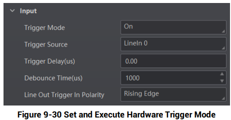
Set and Execute Hardware Trigger ModeSteps1. Click I/O Control Settings → Input → Trigger Mode.2. Select On as Trigger Mode.3. Select the specific line as Trigger Source according to actual demands.

4. Set Debounce Time and Line Out Trigger In Polarity according to actual demands.

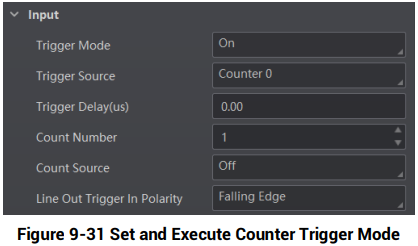
Set and Execute Counter Trigger ModeCounter specifies that the trigger source will be generated after the set number of valid signals appears. For example, if you set the Count Number to 3, the trigger source will be generated after 3 signals appear.Steps1. Click I/O Control Settings → Input → Trigger Mode.2. Select On as Trigger Mode.3. Select Counter 0 as Trigger Source.4. Set Trigger Delay, Count Number, Count Source and Line Out Trigger In Polarity according to actual demands.
Set and Execute TCP Trigger ModeTCP start specifies the TCP server as the source for the trigger signal. When the server receives the specified string text, the trigger signal will be outputted.Steps1. Go to I/O Control Settings → Input → Trigger Mode.2. Select On as Trigger Mode.3. Select TCP Start as Trigger Source.4. Set following parameters according to actual demands.● TCP Trigger Port: It sets the host port of TCP trigger.● TCP Start Trigger Text: It sets the trigger text of TCP start, and it is Start by default.
Set and Execute UDP Trigger ModeUDP start specifies the UDP server as the source for the trigger signal. When the server receives the specified string text, the trigger signal will be outputted.
Steps1. Go to I/O Control Settings → Input → Trigger Mode.2. Select On as Trigger Mode.3. Select UDP Start as Trigger Source.4. Set following parameters according to actual demands.● UDP Trigger Port: It sets the host port of UDP trigger.● UDP Start Trigger Text: It sets the trigger text of UDP start, and it is Start by default.Set and Execute Serial Port Trigger ModeSerial start specifies the serial port as the source for the trigger signal. When the serial port receives the specified string text, the trigger signal will be outputted.
Steps1. Go to I/O Control Settings → Input → Trigger Mode.2. Select On as Trigger Mode.3. Select Serial Start as Trigger Source.4. Set Serial Baudrate, Serial Data Bits, Serial Parity, and Serial Stop Bits.5. Set Serial Start Trigger Text that configures the trigger text of serial port start, and it is Start by default.
Set and Execute USB Trigger ModeSteps1. Go to I/O Control Settings → Input → Trigger Mode.2. Select On as Trigger Mode.3. Select USB Start as Trigger Source.4. Set USB Baudrate, USB Data Bits, USB Parity, USB Stop Bits, and USB Start Trigger Text according to actual demands.
Set and Execute Self Trigger ModeSelf trigger allows you to trigger the device according to the trigger period you configured.Steps1. Click I/O Control Settings → Input → Trigger Mode.2. Select On as Trigger Mode.3. Select Self Trigger as Trigger Source, set Self Trigger Period and Self Trigger Count.
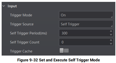

Set and Execute Response TiggerSteps1. Click I/O Control Settings → Input → Trigger Mode.2. Select On as Trigger Mode.3. Select Response Trigger as Trigger Source, and set Trigger Sensitivity accordingly.
9.6.4 Stop TriggerThe device supports stopping trigger via TCP, UDP, I/O, serial port and USB. You can also set code reading timeout duration or max. code amount to be read to stop trigger. After stopping trigger is completed, the device cannot make response to trigger again.


Stop Trigger via TCPWhen the TCP server receives the specified string text, the trigger will be stopped.Steps1. Go to I/O Control Settings → Stop Trigger.2. Enable TCP Stop Trigger Enable.3. Set following parameters according to actual demands.● TCP Trigger Port: It is 2001 by default.● TCP Stop Trigger Format: It is Str by default.● TCP Stop Trigger Text: It sets the stop trigger text, and it is Stop by default.
Stop Trigger via UDPWhen the UDP receives the specified string text, the trigger will be stopped.Steps1. Go to I/O Control Settings → Stop Trigger.2. Enable UDP Stop Trigger Enable.3. Set following parameters according to actual demands.● UDP Trigger Port: It is 2002 by default.● UDP Stop Trigger Format: It is Str by default.● UDP Stop Trigger Text: It sets the stop trigger text, and it is Stop by default.Stop Trigger via IOStopping trigger via IO allows you to select hardware or software trigger source to stop the device from acquiring images.Steps1. Go to I/O Control Settings → Stop Trigger.2. Enable IO Stop Trigger Enable.3. Select sources from LineIn 0/1/2/3 and Software Trigger End as IO Stop Trigger Selector.4. (Optional) Set trigger activation if LineIn 0/1/2/3 is selected as IO Stop Trigger Selector.5. (Optional) Click Execute in Software Stop Trigger to stop trigger if Software Trigger End is selected as IO Stop Trigger Selector.
Stop Trigger via Serial PortWhen the specified serial port receives the specified string text, the trigger will be stopped.Steps1. Go to I/O Control Settings → Stop Trigger.2. Enable Serial Stop Trigger Enable.3. Set following parameters according to actual demands.● Serial Stop Trigger Text: It sets the trigger text of serial port stop, and it is Stop by default.● Serial Baud Rate: It sets the baud rate of the serial port, and it is 9600 by default.● Serial Data Bits: It sets the data bits of the serial port, and it is 8 by default.● Serial Parity: It sets the parity of the serial port, and it is No Parity by default.● Serial Stop Bits: It sets the stop bits of the serial port, and it is 1 by default.
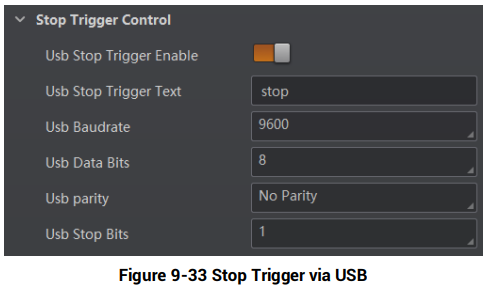
Stop Trigger via USBThe USB stop trigger function means that the device receives USB commands from the external device to stop image acquisition. At this time, the device acts as a USB server to receive commands, and the external device communicating with it acts as a USB client to send commands.Go to Feature Tree, find Stop Trigger Control, enable USB Stop Trigger Enable, set USB Stop Trigger Text, USB Baudrate, USB Data Bits, USB Parity, and USB Stop Bits according to actual demands.
Stop Trigger via Timeout DurationWhen the trigger time reaches the specified maximum value (ms), the trigger will be stopped. You can enable TimeOut Stop Trigger Enable, and set Maximum Output Limited Time according to actual demands.


Stop Trigger via Code NumberThis function means that the code quantity outputted by the device is restricted to the settings you configured here.You can enable CodeNum Stop Trigger Enable, and set CodeNum Stop Trigger Min and CodeNum Stop Trigger Max according to actual demands.
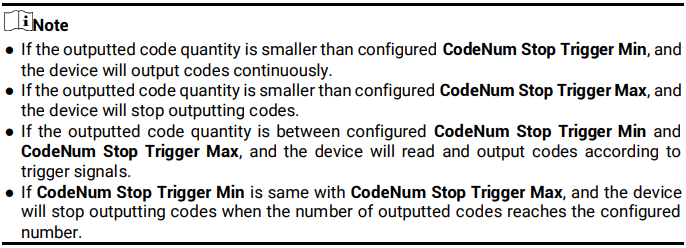
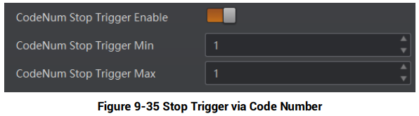
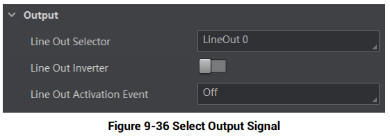
9.7 Signal Output Settings9.7.1 Select Output SignalThe device’s output signal can control external devices like PLC, flashingaiming light, etc.laser, Clicksmart I/Otune, Controltune Settingsbutton, →focus, Outputauto →focus, LineROI Outfocus, Selectorself-adaptive toadjustment, selecttest output signal.pattern

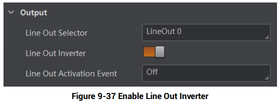
9.7.2 Enable Line InverterThe line inverter function allows the device to invert the electrical signal level of an I/O line, and meets requirements of different devices for high or low electrical signal level.You can go to I/O Control Settings → Output → Line Out Inverter to enable it.

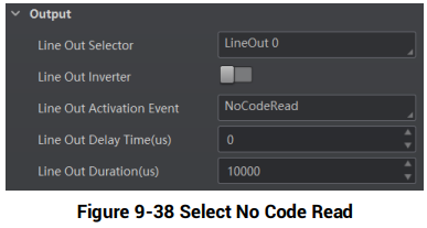
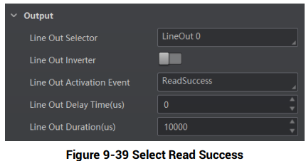
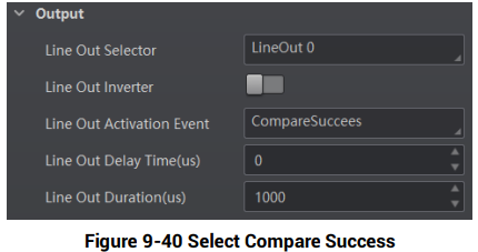
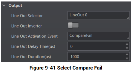
9.7.3 Set Event SourceThe device supports outputting different trigger signals according to the event source you select. Click I/O Control Settings → Output → Line Out Activation Event to select event source.The device supports following event sources, including Off, NoCodeRead, ReadSuccess, Compare Success, and Compare Fail.

● No Code Read: If no code read by the device, the output signal will be triggered.● Read Success: If the code is read by the device, the output signal will be triggered.● Compare Success: If data comparison is successful, the output signal will be triggered.● Compare Fail: If data comparison is failed, the output signal will be triggered.● Command Control IO: It is controlled by the communication strings.

Select No Code ReadIf you select No Code Read as Line Out Activation Event, and you can set its output delay time and duration.● Line Out Delay Time: It sets the delay time for outputting the output signal.● Line Out Duration: It sets the time duration of the output signal.
Select Read SuccessIf you select Read Success as Line Out Activation Event, and you can set its output delay time and duration.● Line Out Delay Time: It sets the delay time for outputting the output signal.● Line Out Duration: It sets the time duration of the output signal.
Select Compare SuccessIf you select Compare Success as Line Out Activation Event, and you can set its output delay time and duration.● Line Out Delay Time: It sets the delay time for outputting the output signal.● Line Out Duration: It sets the time duration of the output signal.
Select Compare FailIf you select Compare Fail as Line Out Activation Event, and you can set its output delay time and duration.● Line Out Delay Time: It sets the delay time for outputting the output signal.● Line Out Duration: It sets the time duration of the output signal.
Select Command Control IOIf you select Command Control IO as Line Out Activation Event, and you do not need to set any parameters.● Control Start Str: It sets the start string of command control.● Control Stop Str: It sets the stop string of command control.● Line Out Delay Time: It sets the delay time for outputting the output signal.● Line Out Duration: It sets the time duration of the output signal.
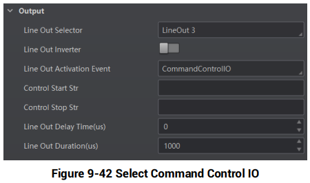
9.7.4 Set Buzzer

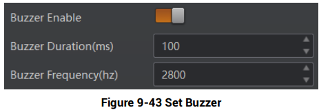
The buzzer is used to indicate the device’s operation status, and you can set the buzzer function according to actual demands.
Steps1. Right click the device in Device Connection, and click Feature Tree.2. Go to Trigger and IO Control→ Buzzer Enable, and enable Buzzer Enable.

3. Set Buzzer Duration (ms) and Buzzer Frequency (hz) according to actual demands.
9.8 Communication SettingsThe communication protocol is used to transmit and output code reading result and image. The communication protocol is related to the device modes. With various device modes, the device supports different communication protocols and corresponding parameters.● If the device’s operation mode is Test or Raw, and it only supports SmartSDK protocol and no parameter settings are required.● If the device’s operation mode is Normal, and it supports SmartSDK, TCP Client, Serial, FTP, TCP Server, Profinet, MELSEC/SLMP, Ethernet/IP, ModBus, UDP, Fins and USB communication protocols, and you need to set corresponding parameters.
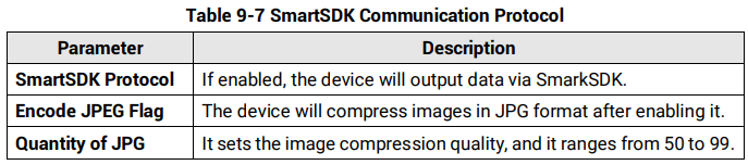
9.8.1 Set SmartSDKIf you select SmartSDK as the communication protocol, you can configure the following parameters:
9.8.2 Set TCP ClientIf you select TCP Client as the communication protocol, you can configure the following parameters:
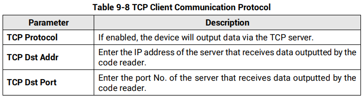
9.8.3 Set SerialIf you select Serial as the communication protocol, you can configure the following parameters:
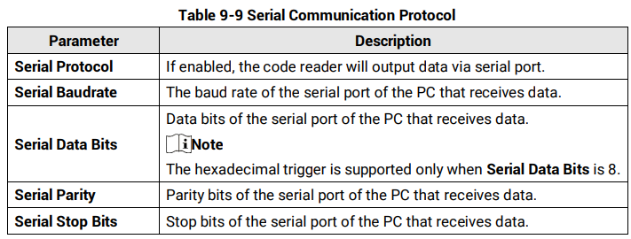
9.8.4 Set FTPIf you select FTP as the communication protocol, you can configure the following parameters:
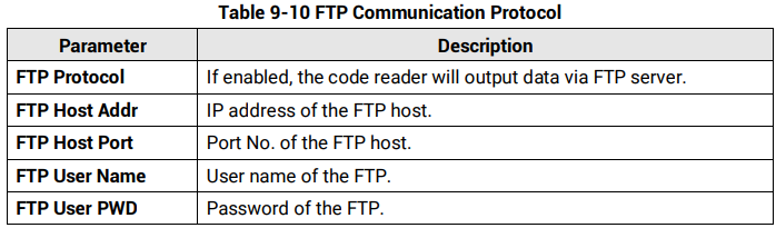
9.8.5 Set TCP ServerIf you select TCP Server as the communication protocol, you can configure the following parameters:

9.8.6 Set ProfinetIf you select Profinet as the communication protocol, you can configure the following parameters:

9.8.7 Set MELSEC/SLMPIf you select Melsec/SLMP as the communication protocol, you can configure the following parameters:
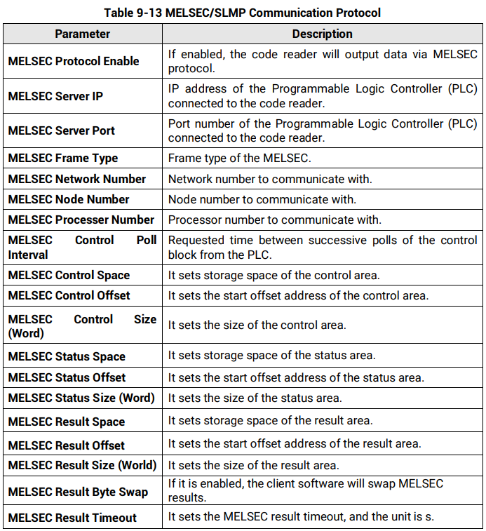
9.8.8 Set Ethernet/IPIf you select EthernetIp as the communication protocol, you can configure the following parameters:

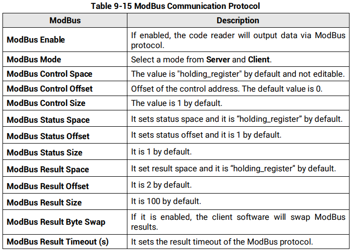
9.8.9 Set ModBusIf you select Modbus as the communication protocol, you can configure the following parameters:
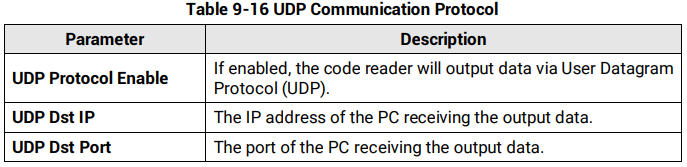
9.8.10 UDPIf you select UDP as the communication protocol, you can configure the following parameters:
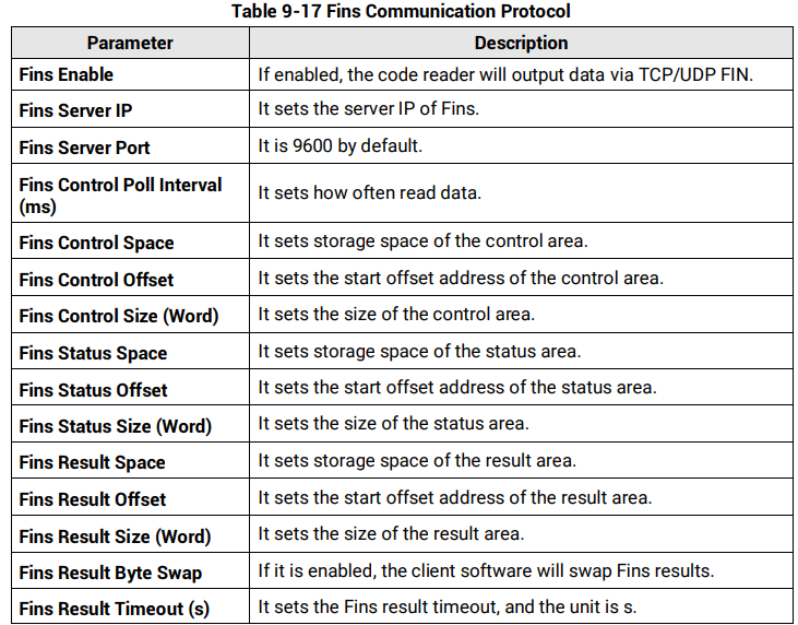
9.8.11 FinsIf you select Fins as the communication protocol, you can configure the following parameters:
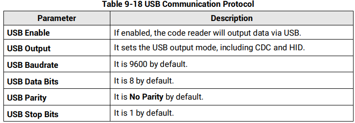
9.8.12 USBIf you select USB as the communication protocol, you can configure the following parameters:
9.9 Data Processing SettingsIn Data Processing, you can set filter rules for reading codes and other data processing related parameters.

9.9.1 Set Filter RuleYou can set rules via Filter Rule to filter unwanted codes to improve the reading efficiency.
Normal Filter ModeIf the device’s operation mode is normal, trigger mode is on, filter mode is normal, and youcan set following parameters according to actual demands:● Instant Output Mode Enable: If enabled, the device will output barcode data immediatelyonce a code is read. If not enabled, the barcode data will be outputted after the devicetrigger process ends.

● Min. Output Time(ms) : Define the minimum time duration (unit: ms) for data output. The duration starts from trigger time. Note: The parameter is only available when the running mode is set to Normal mode and the trigger mode is enabled.

● Min. Code Length: If the length of a barcode is shorter (in terms of the number of characters) than the configured value, the device will NOT parse the barcode.For example, if you set the value to 6, the device will not parse the barcodes which contain fewer than 6 characters.

● Max. Code Length: If the length of a barcode is longer (in terms of the number of characters) than the configured value, the device will NOT parse the barcode.For example, if you set the value to 9, the device will not parse the barcodes which contain more than 9 characters.

● Numeral Filter: If enabled, the device will only parse and read the numeral contents of the barcodes, and the non-numeral contents will be filtered out.● Begin with Specific Character for Result: enabled, the device will only read the barcodes which begin with a specific character string.● Begins with: Enter the character string.● Include Specific Character in Barcode: If enabled, the device will only read the barcodes which include a specific character string.● Character: Enter the character string.● Exclude Specific Character in Barcode: If enabled, the device will only read the barcodes without a specific character string.● Character: Enter the character string.● Remove Duplicate By ROI: If it is enabled, the device will filter information based on drawn ROIs.● Read Times Threshold: If the reading results of a barcode is same for the configured times, the barcode will be regarded as valid and its data will be outputted. Or the barcode will be regarded as invalid and its data will not be outputted.● De-duplication Enable By Trigger: If it is enabled, the repeated code information will be filtered within specific trigger times. You can set trigger times in De-duplication Windows Size, and its default value is 1.● De-duplication By ROI: If it is enabled, the device will filter information based on drawn ROIs.● Code Start Offset Num: It cuts the specific length of code contents from starting, and the remaining part will be outputted.● Code End Offset Num: It cuts the specific length of code contents from ending, and the remaining part will be outputted.
Regular Expression Filter ModeThe device supports filtering codes via the regular expression.Steps1. Select Regular Expression as the Filter Mode, and click Set in Regular Expression Filter to enter regular expression filter settings window.2. Import local files or add customized filter rules to set the regular expression.● Import local files: Click Import to import local .xml files, and click OK to finish.
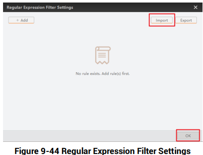
● Add customized filter rule: Click Add and set related parameters in the popped-up window, and click OK after configuring parameters.
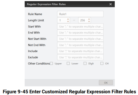
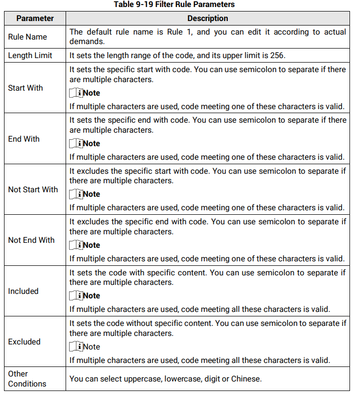
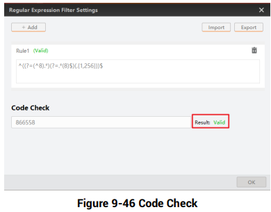
3. After setting filter rule, enter the code in Code Check to check if the filter rule is successful.

4. (Optional) Click 
to delete unwanted filter rules.5. (Optional) Click Export to export configured filter rules to local PC

9.9.2 Data Processing SettingsYou can configure the contents contained in the output barcode information.
SmartSDK● NoRead Image Index: It sets the specific image that is outputted when no code information is read. For example, if you set this parameter as 5, and the 5th image will be output.● One By One Enable: If it is enabled, the device will send one piece of code information each time in accordance with the specified interval. You can set the interval via One By One Interval and the default value 100 ms.
FTPWhen the communication protocol is FTP, set the following parameters of data processing:● NoRead Image Index: It sets the specific image that is outputted when no code information is read. For example, if you set this parameter as 5, and the 5th image will be output.● One By One Enable: If it is enabled, the device will send one piece of code information each time in accordance with the specified interval. You can set the interval via One By One Interval and the default value 100 ms.● Local Save Picture Mode: It includes Off, NoRead, and Insufficient Code. You can select NoRead to let the device save images when no code is read.● Local Picture Type: Specify the type of pictures saved locally. You can select JPEG or BMP.● Output Retrans Enable: Enable to allow data re-transmission. Specify the limit of retransmission attempts in Output Retrans Number.● FTP Picture Name Format: Click 
to select one or multiple items to be contained in the picture name. The selected items will be displayed in the frame. You can also enter more contents directly in the frame.● FTP Transmission Conditions: Set the condition to upload the data outputted by the device to FTP server.○ All: Always upload the data.○ ReadBarcode: Upload the data only when the barcode is read by the device.○ NoReadBarcode: Upload the data only when no barcode is read by the device.● FTP Transmission Result Contain: Select contents to upload to the FTP server.○ JustResult: Only upload the content of the barcode.○ JustPicture: Only upload the barcode image.○ ResultAndPicture: Upload both the content of the barcode and the barcode image.● FTP Time Format: Select a format type from the drop-down list for the time stamp contained in the file name.

TCP Client / Serial / TCP Server / Profinet / MELSEC / EthernetIp / Modbus / UDP / FINS/ USB
When the communication protocol is TCP Client / Serial / TCP Server / Profinet / MELSEC / EthernetIp / Modbus / UDP / FINS/ USB, set the following parameters of data processing.

● NoRead Image Index: It sets the specific image that is outputted when no code information is read. For example, if you set this parameter as 5, and the 5th image will be output.● One By One Enable: If it is enabled, the device will send one piece of code information each time in accordance with the specified interval. You can set the interval via One By One Interval and the default value 100 ms.● Local Save Picture Mode: It includes Off, NoRead, and Insufficient Code. You can select NoRead to let the device save images when no code is read.● *** Output Format: Click 
to select one or multiple items to be contained in the picture name. The selected items will be displayed in the frame. You can also enter more contents directly in the frame.
● *** Output Noread Enable: Enable this to set the default output content if no barcode is read during transmission. Edit the output text in Output NoRead Text.● *** Output Start Text: The contents of the start part of the data outputted. You can set the contents as desired.● *** Output Stop Text: The contents of the end part of the data outputted. You can set the contents as desired.● *** Output Barcode Enter Character Enable: Whether to show input character in the data.● *** Output Barcode Newline Character Enable: Whether to show new-line character in the data.
9.10 Set MulticastThe multicast function is used to let multiple devices have the same trigger number when they are acquiring images and analyzing codes at the same time. When each device sends the trigger number and outputted images to the code reading platform, the platform will integrate the images with the same trigger number as the information of the same package. The main principle of the multicast function is to set one main device among multiple devices, and remaining devices are called sub devices. As the first triggered device, the main device sends trigger numbers to sub devices each time, and sub devices replace their trigger numbers with received ones so that all devices have the same trigger numbers.Follow the steps below to set multicast function according to actual demands.
Steps1. Right click the device in Device Connection, and click Feature Tree.2. Go to Multi Camera Control, set one device as Main in Multi Camera Mode according to actual demands.

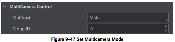
3. Set GroupID.

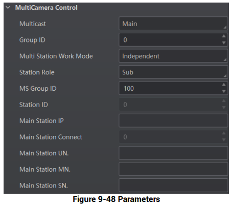
9.11 Main-Sub NetworkingWhen multiple devices acquire images and parse codes at the same time, the main-sub networking function enables multiple devices to work together.The main principle of main-sub networking is to set one of the multiple devices as the main device (main station), and the other devices as sub devices (sub station). The sub devices send the code results to the main device that integrates or forwards, and sends the code results to the connected PC or client software to realize the collaborative work function of multiple devices.
Before You StartMake sure that the device mode is Normal and Tigger Mode is On before using this function.

Steps1. Go to Multi Camera Control, and select Multi Station Work Mode according to actual demands.● Off: This function is disabled.● Independent: The main device and the sub devices are triggered respectively, and the sub devices send the code reading result to the main device. The main device directly formats and outputs the sub devices’ data according to the formatting rules without data processing. It is mainly used for the scenario of multiple assembly lines.● Cooperation: The main device and the sub devices use the same trigger, the sub devices send the code reading result to the main device for data processing, and then format and output the data after the fusion of the main and sub devices according to the formatting rules. It is mainly used to the scenario where the field of view is insufficient, and multiple codes are read together to integrate the output. In most cases, this mode is used.2. Set role for different devices in Station Role. Main is the main device, and Sub is the sub device

3. Set Station Port to configure the main station’s port number and communicate with the sub station.4. (Optional) Enable Client Display Sub Enable to let the main device display the code reading images from the sub station.

5. Set MS Group ID ranging from 100 to 200 to configure the main-sub networking group ID.

6. (Optional) View enumerated sub station quantity via Sub Station Total as a main station role.7. (Optional) View sub station information after entering Query Sub Station ID as a main station role.● Sub Station IP: The IP information of the sub station.● Sub Station Connect: The connection status of the sub station. 1 stands for normal data transmission. Otherwise, it is disconnected.● Sub Station UN: The user name information of the sub station.● Sub Station MN: The product model information of the sub station.● Sub Station SN: The serial number of the sub station.8. (Optional) View main station information when the Station Role is Sub.● Main Station IP: The IP information of the main station.● Main Station Connect: The connection status of the main station. 1 stands for normal data transmission. Otherwise, it is disconnected.● Main Station UN: The user name information of the main station.● Main Station MN: The product model information of the main station.● Main Station SN: The serial number of the main station.
9.12 Contrast Control Settings

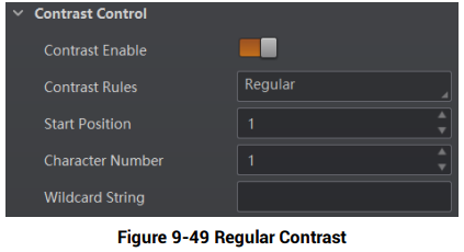
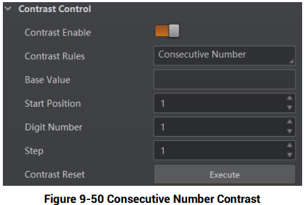
The contrast control function compares the data that the device reads with preset data and outputs contrast result. The result can be used as the event source of trigger signal, including Contrast Success and Contrast Fail. This function has two ways to contrast, including regular contrast and consecutive number contrast.
Regular ContrastThe regular contrast requires you to set code contents in advance, and the client software will contrast the data that the device reads with preset contents and outputs comparison result.Steps1. Right click the device in Device Connection, and click Feature Tree.2. Go to Contrast Control, enable Contrast Enable, and select Regular as Contrast Rules.3. Set Start Position that means the stating position of the comparison.4. Set Character Number that means the comparison quantity.5. Set code contents in Wildcard String.

Consecutive Number ContrastThe consecutive number contrast requires you to set consecutive code rules, and the client software will contrast the data that the device reads with preset rules and outputs contrast result.Steps1. Right click the device in Device Connection, and click Feature Tree.2. Go to Contrast Control, enable Contrast Enable, and select Consecutive Number as Compare Rules.3. Set Start Position that means the stating position of the comparison.4. Set Digital Number that means the comparison quantity.5. Set Step that means the client software will increase or decrease the preset value after each comparison according the step you set.

6. (Optional) Click Execute in Contrast Reset to reset comparison. After that, the client software will use the first code it reads as the preset value.Here we take start position (3), digital number (2) and step (2) as an example to explain the consecutive number comparison:● If the first code that the device reads is ur96k, and then the preset value is 96. The preset value increases to 98 (96+2).● If the second code is yr98kjkfd, and comparison succeeds. The preset value increases to 100 (98+2).● If the third code is kl99fjkd, and comparison fails. The preset value does not increase.● If the fourth code is kl00djf, and comparison succeeds. The preset value increases to 02 (00+2).
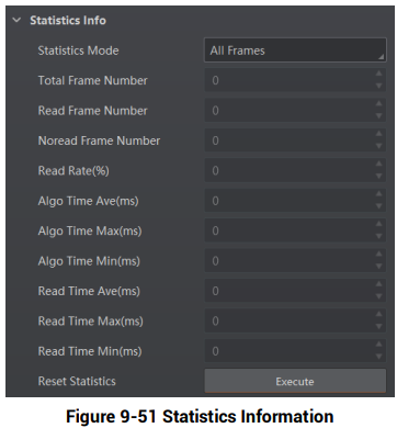
9.13 Statistics InformationThe statistics information in the feature tree helps you to count data related with code reading.

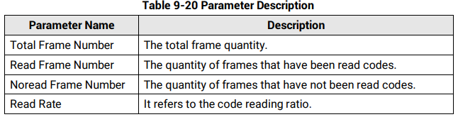
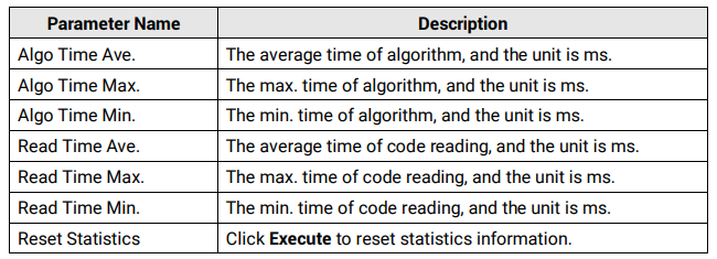
Steps1. Right click the device in Device Connection, and click Feature Tree.2. Go to feature tree, find Statistics Info., and select Statistics Mode:● All Frames means the client software will display all data since the device is powered on.● Latest Frames means the client software will display data of the last 10 frames.3. View related parameters.4. (Optional) Click Execute in Reset Statistics to reset statistics information.
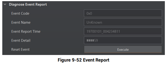
9.14 Diagnose Event ReportThe diagnose event report function monitors memory and CPU usage rate, and let you know when there is a crash, higher CPU usage rate, insufficient memory, and other events.Steps1. Right click the device in Device Connection, and click Feature Tree.2. Go to feature tree, find Diagnose Event Report.3. View relation information.4. (Optional) Click Execute in Reset Event to clear all information.
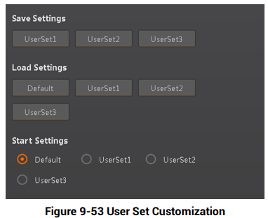
9.15 User Set CustomizationIn Configuration Management, you can set and manage the user set. A user set is a group of parameter values with all the settings needed to control the device, and you can save, load and switch different user sets.● Save Settings: If you have set the device parameters as desired, you can save them into the user set. Go to Config Management → Save Settings, and click UserSet1, UserSet2, or UserSet3 to save the current device settings.● Load Settings: You can load the user set to restore the device to the saved group of parameter values again if required. Go to Config Management → Load Settings, and click Default, UserSet1, UserSet2, or UserSet3 to load settings.

● Start Settings: The selected user set will be automatically loaded after the device being powered on. For example, if you select Default, the device parameter settings will be restored to the factory settings.