
9. Device Settings – Part 4 (Communication and Data Processing)
Streszczenie: Ustawienia ID2000 cz. 4: protokoły komunikacyjne (SmartSDK, TCP Client/Server, Serial, FTP, Profinet, MELSEC/SLMP, Ethernet/IP, ModBus, UDP, Fins, USB) oraz przetwarzanie danych – reguły filtrowania (w tym wyrażenia regularne) i format wyników.
EN: ID2000 settings part 4: communication protocols (SmartSDK, TCP Client/Server, Serial, FTP, Profinet, MELSEC/SLMP, Ethernet/IP, ModBus, UDP, Fins, USB) and data processing – filter rules (incl. regular expressions) and result format.
Dotyczy: przemysłowy czytnik kodów Hikrobot serii ID2000 (typy I–VII; Fast Ethernet, USB lub RS-232; obsługa przez klienta IDMVS i kody konfiguracyjne)
Źródło: dokumentacja producenta (Hikrobot ID2000 Series Industrial Code Reader User Manual); tabele i uwagi przepisane z obrazów na tekst; opisy rysunków – opracowanie Multiprojekt
Rozdział 9 „Device Settings” – części: Part 1 – Feature Tree, Reading Mode, Image Quality | Part 2 – Code Algorithm and Line Mode | Part 3 – Signal Input and Output | Part 4 – Communication and Data Processing | Part 5 – Multicast, Contrast, Statistics, Events, User Set
← poprzednia część · następna część →
9.8 Communication Settings
The communication protocol is used to transmit and output code reading result and image. The communication protocol is related to the device modes. With various device modes, the device supports different communication protocols and corresponding parameters.
- If the device’s operation mode is Test or Raw, and it only supports SmartSDK protocol and no parameter settings are required.
- If the device’s operation mode is Normal, and it supports SmartSDK, TCP Client, Serial, FTP, TCP Server, Profinet, MELSEC/SLMP, Ethernet/IP, ModBus, UDP, Fins and USB communication protocols, and you need to set corresponding parameters.
Note:
- The supported communication protocols may differ by device models.
- The type VII device supports SmartSDK, USB and Serial only. For other device types, the device with USB data interface supports SmartSDK and USB only, and the device with fast Ethernet supports all communication protocols apart from USB.
- The specific parameters of communication protocols may differ by device models.
9.8.1 Set SmartSDK
If you select SmartSDK as the communication protocol, you can configure the following parameters:
Table 9-7 SmartSDK Communication Protocol
| Parameter | Description |
|---|---|
| SmartSDK Protocol | If enabled, the device will output data via SmartSDK. |
| Encode JPEG Flag | The device will compress images in JPG format after enabling it. |
| Quality of JPG | It sets the image compression quality, and it ranges from 50 to 99. |
The source table lists the last parameter as “Quantity of JPG”.
9.8.2 Set TCP Client
If you select TCP Client as the communication protocol, you can configure the following parameters:
Table 9-8 TCP Client Communication Protocol
| Parameter | Description |
|---|---|
| TCP Protocol | If enabled, the device will output data via the TCP server. |
| TCP Dst Addr | Enter the IP address of the server that receives data outputted by the code reader. |
| TCP Dst Port | Enter the port No. of the server that receives data outputted by the code reader. |
9.8.3 Set Serial
If you select Serial as the communication protocol, you can configure the following parameters:
Table 9-9 Serial Communication Protocol
| Parameter | Description |
|---|---|
| Serial Protocol | If enabled, the code reader will output data via serial port. |
| Serial Baudrate | The baud rate of the serial port of the PC that receives data. |
| Serial Data Bits | Data bits of the serial port of the PC that receives data. Note: The hexadecimal trigger is supported only when Serial Data Bits is 8. |
| Serial Parity | Parity bits of the serial port of the PC that receives data. |
| Serial Stop Bits | Stop bits of the serial port of the PC that receives data. |
9.8.4 Set FTP
If you select FTP as the communication protocol, you can configure the following parameters:
Table 9-10 FTP Communication Protocol
| Parameter | Description |
|---|---|
| FTP Protocol | If enabled, the code reader will output data via the FTP server. |
| FTP Host Addr | IP address of the FTP host. |
| FTP Host Port | Port No. of the FTP host. |
| FTP User Name | User name of the FTP. |
| FTP User PWD | Password of the FTP. |
9.8.5 Set TCP Server
If you select TCP Server as the communication protocol, you can configure the following parameters:
Table 9-11 TCP Server Communication Protocol
| Parameter | Description |
|---|---|
| TCP Server Enable | If enabled, the code reader will output data via the TCP server. |
| TCP Server Port | The port No. of the TCP server that receives data outputted by the code reader. |
9.8.6 Set Profinet
If you select Profinet as the communication protocol, you can configure the following parameters:
Table 9-12 Profinet Communication Protocol
| Parameter | Description |
|---|---|
| Profinet Enable | If enabled, the device will output data via the Profinet protocol. |
| Profinet Device Name | Enter the name of the code reader, which is used for code reader recognition in Profinet protocol communication. |
9.8.7 Set MELSEC/SLMP
If you select Melsec/SLMP as the communication protocol, you can configure the following parameters:
Table 9-13 MELSEC/SLMP Communication Protocol
| Parameter | Description |
|---|---|
| MELSEC Protocol Enable | If enabled, the code reader will output data via the MELSEC protocol. |
| MELSEC Server IP | IP address of the Programmable Logic Controller (PLC) connected to the code reader. |
| MELSEC Server Port | Port number of the Programmable Logic Controller (PLC) connected to the code reader. |
| MELSEC Frame Type | Frame type of the MELSEC. |
| MELSEC Network Number | Network number to communicate with. |
| MELSEC Node Number | Node number to communicate with. |
| MELSEC Processer Number | Processor number to communicate with. |
| MELSEC Control Poll Interval | Requested time between successive polls of the control block from the PLC. |
| MELSEC Control Space | It sets the storage space of the control area. |
| MELSEC Control Offset | It sets the start offset address of the control area. |
| MELSEC Control Size (Word) | It sets the size of the control area. |
| MELSEC Status Space | It sets the storage space of the status area. |
| MELSEC Status Offset | It sets the start offset address of the status area. |
| MELSEC Status Size (Word) | It sets the size of the status area. |
| MELSEC Result Space | It sets the storage space of the result area. |
| MELSEC Result Offset | It sets the start offset address of the result area. |
| MELSEC Result Size (Word) | It sets the size of the result area. |
| MELSEC Result Byte Swap | If it is enabled, the client software will swap MELSEC results. |
| MELSEC Result Timeout | It sets the MELSEC result timeout, and the unit is s. |
9.8.8 Set Ethernet/IP
If you select EthernetIp as the communication protocol, you can configure the following parameters:
Table 9-14 Ethernet/IP Communication Protocol
| Parameter | Description |
|---|---|
| Ethernet/IP Enable | If enabled, the code reader will output data via the Ethernet/IP protocol. |
9.8.9 Set ModBus
If you select Modbus as the communication protocol, you can configure the following parameters:
Table 9-15 ModBus Communication Protocol
| ModBus | Description |
|---|---|
| ModBus Enable | If enabled, the code reader will output data via the ModBus protocol. |
| ModBus Mode | Select a mode from Server and Client. |
| ModBus Control Space | The value is “holding_register” by default and not editable. |
| ModBus Control Offset | Offset of the control address. The default value is 0. |
| ModBus Control Size | The value is 1 by default. |
| ModBus Status Space | It sets the status space and it is “holding_register” by default. |
| ModBus Status Offset | It sets the status offset and it is 1 by default. |
| ModBus Status Size | It is 1 by default. |
| ModBus Result Space | It sets the result space and it is “holding_register” by default. |
| ModBus Result Offset | It is 2 by default. |
| ModBus Result Size | It is 100 by default. |
| ModBus Result Byte Swap | If it is enabled, the client software will swap ModBus results. |
| ModBus Result Timeout (s) | It sets the result timeout of the ModBus protocol. |
9.8.10 UDP
If you select UDP as the communication protocol, you can configure the following parameters:
Table 9-16 UDP Communication Protocol
| Parameter | Description |
|---|---|
| UDP Protocol Enable | If enabled, the code reader will output data via User Datagram Protocol (UDP). |
| UDP Dst IP | The IP address of the PC receiving the output data. |
| UDP Dst Port | The port of the PC receiving the output data. |
9.8.11 Fins
If you select Fins as the communication protocol, you can configure the following parameters:
Table 9-17 Fins Communication Protocol
| Parameter | Description |
|---|---|
| Fins Enable | If enabled, the code reader will output data via TCP/UDP FINS. |
| Fins Server IP | It sets the server IP of Fins. |
| Fins Server Port | It is 9600 by default. |
| Fins Control Poll Interval (ms) | It sets how often data is read. |
| Fins Control Space | It sets the storage space of the control area. |
| Fins Control Offset | It sets the start offset address of the control area. |
| Fins Control Size (Word) | It sets the size of the control area. |
| Fins Status Space | It sets the storage space of the status area. |
| Fins Status Offset | It sets the start offset address of the status area. |
| Fins Status Size (Word) | It sets the size of the status area. |
| Fins Result Space | It sets the storage space of the result area. |
| Fins Result Offset | It sets the start offset address of the result area. |
| Fins Result Size (Word) | It sets the size of the result area. |
| Fins Result Byte Swap | If it is enabled, the client software will swap Fins results. |
| Fins Result Timeout (s) | It sets the Fins result timeout, and the unit is s. |
9.8.12 USB
If you select USB as the communication protocol, you can configure the following parameters:
Table 9-18 USB Communication Protocol
| Parameter | Description |
|---|---|
| USB Enable | If enabled, the code reader will output data via USB. |
| USB Output | It sets the USB output mode, including CDC and HID. |
| USB Baudrate | It is 9600 by default. |
| USB Data Bits | It is 8 by default. |
| USB Parity | It is No Parity by default. |
| USB Stop Bits | It is 1 by default. |
9.9 Data Processing Settings
In Data Processing, you can set filter rules for reading codes and other data processing related parameters.
Note: The specific parameters may differ by device models and firmware versions.
9.9.1 Set Filter Rule
You can set rules via Filter Rule to filter unwanted codes to improve the reading efficiency.
Normal Filter Mode
If the device’s operation mode is normal, trigger mode is on, filter mode is normal, and you can set following parameters according to actual demands:
- Instant Output Mode Enable: If enabled, the device will output barcode data immediately once a code is read. If not enabled, the barcode data will be outputted after the device trigger process ends.
Note: The parameter is only available when the running mode is set to Normal mode and the trigger mode is enabled.
- Min. Output Time(ms) : Define the minimum time duration (unit: ms) for data output. The duration starts from trigger time. Note: The parameter is only available when the running mode is set to Normal mode and the trigger mode is enabled.
Note: The parameter is only available when the running mode is set to Normal mode and the trigger mode is enabled.
- Min. Code Length: If the length of a barcode is shorter (in terms of the number of characters) than the configured value, the device will NOT parse the barcode.
For example, if you set the value to 6, the device will not parse the barcodes which contain fewer than 6 characters.
Note: The valid value of the parameter is from 1 to 256.
- Max. Code Length: If the length of a barcode is longer (in terms of the number of characters) than the configured value, the device will NOT parse the barcode.
For example, if you set the value to 9, the device will not parse the barcodes which contain more than 9 characters.
Note: The valid value of the parameter is from 1 to 256.
- Numeral Filter: If enabled, the device will only parse and read the numeral contents of the barcodes, and the non-numeral contents will be filtered out.
- Begin with Specific Character for Result: enabled, the device will only read the barcodes which begin with a specific character string.
- Begins with: Enter the character string.
- Include Specific Character in Barcode: If enabled, the device will only read the barcodes which include a specific character string.
- Character: Enter the character string.
- Exclude Specific Character in Barcode: If enabled, the device will only read the barcodes without a specific character string.
- Character: Enter the character string.
- Remove Duplicate By ROI: If it is enabled, the device will filter information based on drawn ROIs.
- Read Times Threshold: If the reading results of a barcode is same for the configured times, the barcode will be regarded as valid and its data will be outputted. Or the barcode will be regarded as invalid and its data will not be outputted.
- De-duplication Enable By Trigger: If it is enabled, the repeated code information will be filtered within specific trigger times. You can set trigger times in De-duplication Windows Size, and its default value is 1.
- De-duplication By ROI: If it is enabled, the device will filter information based on drawn ROIs.
- Code Start Offset Num: It cuts the specific length of code contents from starting, and the remaining part will be outputted.
- Code End Offset Num: It cuts the specific length of code contents from ending, and the remaining part will be outputted.
Regular Expression Filter Mode
The device supports filtering codes via the regular expression.
Steps
- Select Regular Expression as the Filter Mode, and click Set in Regular Expression Filter to enter regular expression filter settings window.
- Import local files or add customized filter rules to set the regular expression.
- Import local files: Click Import to import local .xml files, and click OK to finish.
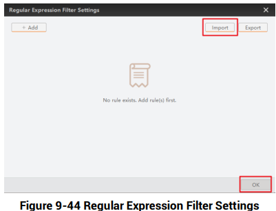
Figure 9-44 Regular Expression Filter Settings
Figure description (text version): Regular Expression Filter Settings window with Add, Import and Export buttons; no rules yet ("No rule exists. Add rule(s) first."); the Import button and the OK button are highlighted in red.
- Add customized filter rule: Click Add and set related parameters in the popped-up window, and click OK after configuring parameters.
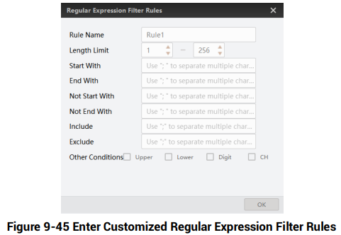
Figure 9-45 Enter Customized Regular Expression Filter Rules
Figure description (text version): Regular Expression Filter Rules dialog: Rule Name Rule1, Length Limit 1–256, fields Start With, End With, Not Start With, Not End With, Include and Exclude (use ";" to separate multiple characters), Other Conditions check boxes Upper, Lower, Digit and CH, OK button.
Table 9-19 Filter Rule Parameters
| Parameter | Description |
|---|---|
| Rule Name | The default rule name is Rule 1, and you can edit it according to actual demands. |
| Length Limit | It sets the length range of the code, and its upper limit is 256. |
| Start With | It sets the specific start of the code. You can use a semicolon to separate multiple characters. Note: If multiple characters are used, code meeting one of these characters is valid. |
| End With | It sets the specific end of the code. You can use a semicolon to separate multiple characters. Note: If multiple characters are used, code meeting one of these characters is valid. |
| Not Start With | It excludes the specific start of the code. You can use a semicolon to separate multiple characters. Note: If multiple characters are used, code meeting one of these characters is valid. |
| Not End With | It excludes the specific end of the code. You can use a semicolon to separate multiple characters. Note: If multiple characters are used, code meeting one of these characters is valid. |
| Included | It sets the code with specific content. You can use a semicolon to separate multiple characters. Note: If multiple characters are used, code meeting all these characters is valid. |
| Excluded | It sets the code without specific content. You can use a semicolon to separate multiple characters. Note: If multiple characters are used, code meeting all these characters is valid. |
| Other Conditions | You can select uppercase, lowercase, digit or Chinese. |
- After setting filter rule, enter the code in Code Check to check if the filter rule is successful.
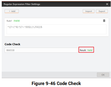
Figure 9-46 Code Check
Figure description (text version): Regular Expression Filter Settings window with one rule (Rule1) and its generated expression; in the Code Check area a test code is entered and the Result field (highlighted in red) shows "valid".
Note: If the filter rule you configured is correct, the result is valid. Otherwise, it is invalid.
- (Optional) Click
 to delete unwanted filter rules.
- (Optional) Click Export to export configured filter rules to local PC
Note: The filter rule parameters of the regular expression may differ by device models and firmware versions.
9.9.2 Data Processing Settings
You can configure the contents contained in the output barcode information.
Note:
- The actual parameters displayed may vary with different communication protocols. For details about communication settings, refer to Communication Settings.
- The device with USB data interface supports SmartSDK and USB only, and the device with fast Ethernet supports all communication protocols apart from USB.
- The specific parameters and parameter order may differ by the device’s operation mode, trigger mode, device models and firmware versions.
SmartSDK
- NoRead Image Index: It sets the specific image that is outputted when no code information is read. For example, if you set this parameter as 5, and the 5th image will be output.
- One By One Enable: If it is enabled, the device will send one piece of code information each time in accordance with the specified interval. You can set the interval via One By One Interval and the default value 100 ms.
FTP
When the communication protocol is FTP, set the following parameters of data processing:
- NoRead Image Index: It sets the specific image that is outputted when no code information is read. For example, if you set this parameter as 5, and the 5th image will be output.
- One By One Enable: If it is enabled, the device will send one piece of code information each time in accordance with the specified interval. You can set the interval via One By One Interval and the default value 100 ms.
- Local Save Picture Mode: It includes Off, NoRead, and Insufficient Code. You can select NoRead to let the device save images when no code is read.
- Local Picture Type: Specify the type of pictures saved locally. You can select JPEG or BMP.
- Output Retrans Enable: Enable to allow data re-transmission. Specify the limit of retransmission attempts in Output Retrans Number.
- FTP Picture Name Format: Click
 to select one or multiple items to be contained in the picture name. The selected items will be displayed in the frame. You can also enter more contents directly in the frame.
- FTP Transmission Conditions: Set the condition to upload the data outputted by the device to FTP server.
- All: Always upload the data.
- ReadBarcode: Upload the data only when the barcode is read by the device.
- NoReadBarcode: Upload the data only when no barcode is read by the device.
- FTP Transmission Result Contain: Select contents to upload to the FTP server.
- JustResult: Only upload the content of the barcode.
- JustPicture: Only upload the barcode image.
- ResultAndPicture: Upload both the content of the barcode and the barcode image.
- FTP Time Format: Select a format type from the drop-down list for the time stamp contained in the file name.
Note: Taking YYYYMMDD_HHMMSSFFF as an example (from left to right): YYYY represents year, MM month, DD date, HH hour, MM minute, SS second, FFF millisecond.
TCP Client / Serial / TCP Server / Profinet / MELSEC / EthernetIp / Modbus / UDP / FINS / USB
When the communication protocol is TCP Client / Serial / TCP Server / Profinet / MELSEC / EthernetIp / Modbus / UDP / FINS/ USB, set the following parameters of data processing.
Note: Here “***” is used to represent the specific protocol name.
- NoRead Image Index: It sets the specific image that is outputted when no code information is read. For example, if you set this parameter as 5, and the 5th image will be output.
- One By One Enable: If it is enabled, the device will send one piece of code information each time in accordance with the specified interval. You can set the interval via One By One Interval and the default value 100 ms.
- Local Save Picture Mode: It includes Off, NoRead, and Insufficient Code. You can select NoRead to let the device save images when no code is read.
- *** Output Format: Click
 to select one or multiple items to be contained in the picture name. The selected items will be displayed in the frame. You can also enter more contents directly in the frame.
- *** Output Noread Enable: Enable this to set the default output content if no barcode is read during transmission. Edit the output text in Output NoRead Text.
- *** Output Start Text: The contents of the start part of the data outputted. You can set the contents as desired.
- *** Output Stop Text: The contents of the end part of the data outputted. You can set the contents as desired.
- *** Output Barcode Enter Character Enable: Whether to show input character in the data.
- *** Output Barcode Newline Character Enable: Whether to show new-line character in the data.
Słowa kluczowe
Hikrobot ID2000, communication protocols, SmartSDK, TCP Client, TCP Server, Serial, FTP, Profinet, MELSEC, SLMP, Ethernet/IP, ModBus, UDP, Fins, USB, filter rule, regular expression, data processing, result format
No comments to display
No comments to display