
4. Connector and Cable
Streszczenie: Złącza i przewody ID2000: definicje pinów złącza M12 17-pin i DB15 dla wersji Fast Ethernet i USB, zaciski 8-pin i 6-pin z kolorami żył, kable typu VII (USB i RS-232) z wolnymi przewodami oraz IO box z rezystorami podciągającymi/ściągającymi.
EN: ID2000 connectors and cables: 17-pin M12 and DB15 pin definitions for fast Ethernet and USB versions, 8-pin and 6-pin terminals with wire colours, type VII USB and RS-232 cables with open lines, and the IO box with pull-up/pull-down resistors.
Dotyczy: przemysłowy czytnik kodów Hikrobot serii ID2000 (typy I–VII; Fast Ethernet, USB lub RS-232; obsługa przez klienta IDMVS i kody konfiguracyjne)
Źródło: dokumentacja producenta (Hikrobot ID2000 Series Industrial Code Reader User Manual); tabele i uwagi przepisane z obrazów na tekst; opisy rysunków – opracowanie Multiprojekt
This section introduces the device’s connector, including fast Ethernet interface, USB interface and RS-232 interface, and the supplied cable in the package.
Note: The device’s connector and connector pin definitions may differ by device models.
4.1 Device with Fast Ethernet Interface
Device with fast Ethernet interface includes type I, type II, type III, type IV, type V, and type VI devices.
Type I, Type II, Type III, and Type IV Devices
Type I, type II, type III, and type IV devices have a 17-pin M12 connector. Refer to the figure and table below for details.
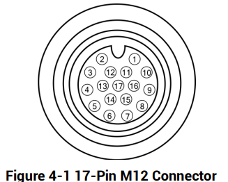
Figure 4-1 17-Pin M12 Connector
Figure description (text version): Front view of the round 17-pin M12 connector: pins 1–11 arranged around the outer ring, pins 12–17 in the inner circle (pin 17 in the centre).
Table 4-1 Pin Definitions (Type I, Type II, Type III and Type IV Devices)
| No. | Signal | I/O Signal Source | Description | Supplied Cable |
|---|---|---|---|---|
| 1 | DC_PWR | – | Direct current power supply positive | 8-pin terminal |
| 2 | GND | Line 0/1/2/3 signal ground | Direct current power supply negative | 8-pin terminal |
| 3 | Reserved | |||
| 4 | RS232_TX | – | RS-232 serial port output | DB9 female serial port |
| 5 | RS232_RX | – | RS-232 serial port input | DB9 female serial port |
| 6 | MDI0+ | – | Fast Ethernet signal MDI0+ | RJ45 Ethernet connector |
| 7 | MDI1- | – | Fast Ethernet signal MDI1- | RJ45 Ethernet connector |
| 8 | GPIO2 | Line 2+ | Non-isolated input | 8-pin terminal |
| 9 | GND | Line 0/1/2/3 signal ground | Direct current power supply negative | 8-pin terminal |
| 10 | GPIO3 | Line 3+ | Non-isolated output | 8-pin terminal |
| 11 | GND | – | Direct current power supply negative | 8-pin terminal |
| 12 | Reserved | |||
| 13 | Reserved | |||
| 14 | MDI0- | – | Fast Ethernet signal MDI0- | RJ45 Ethernet connector |
| 15 | MDI1+ | – | Fast Ethernet signal MDI1+ | RJ45 Ethernet connector |
| 16 | GPIO0 | Line 0+ | It can be configured as input or output, and is input by default. | 8-pin terminal |
| 17 | GPIO1 | Line 1+ | It can be configured as input or output, and is input by default. | 8-pin terminal |
In the source table the title reads “Type VI”; according to the text above, the table applies to type I–IV devices.
Type V Devices
The type V device also has a 17-pin M12 connector. Refer to the figure and table below for details.
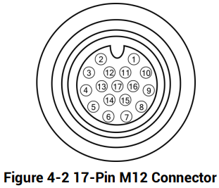
Figure 4-2 17-Pin M12 Connector
Figure description (text version): Front view of the round 17-pin M12 connector of the type V device: pins 1–11 on the outer ring, pins 12–17 in the inner circle.
Table 4-2 Pin Definitions (Type V Device)
| No. | Signal | I/O Signal Source | Description | Supplied Cable |
|---|---|---|---|---|
| 1 | DC_PWR | – | Direct current power supply positive | 8-pin terminal |
| 2 | OUT_COM | LineOut 0/1 signal ground | Output common port | 8-pin terminal |
| 3 | Reserved | |||
| 4 | RS232TX | – | RS-232 serial port output | DB9 female serial port |
| 5 | RS232RX | – | RS-232 serial port input | DB9 female serial port |
| 6 | MDI0+ | – | Fast Ethernet signal MDI0+ | RJ45 Ethernet connector |
| 7 | MDI1- | – | Fast Ethernet signal MDI1- | RJ45 Ethernet connector |
| 8 | OPTO_OUT0 | LineOut 0 signal line | Opto-isolated output 0 | 8-pin terminal |
| 9 | IN_COM | LineIn 0/1 signal ground | Input common port | 8-pin terminal |
| 10 | OPTO_OUT1 | LineOut 1 signal line | Opto-isolated output 1 | 8-pin terminal |
| 11 | GND | – | Direct current power supply negative | 8-pin terminal |
| 12 | Reserved | |||
| 13 | Reserved | |||
| 14 | MDI0- | – | Fast Ethernet signal MDI0- | RJ45 Ethernet connector |
| 15 | MDI1+ | – | Fast Ethernet signal MDI1+ | RJ45 Ethernet connector |
| 16 | OPTO_IN0 | LineIn 0 signal line | Opto-isolated input 0 | 8-pin terminal |
| 17 | OPTO_IN1 | LineIn 1 signal line | Opto-isolated input 1 | 8-pin terminal |
For type I, type II, type III, type IV, and type V devices, you should use the supplied 17-pin cable below to wire them. The cable has a DB9 female serial port connector that corresponds to 4th and 5th pins of the 17-pin M12 connector, and a RJ45 connector that corresponds to 6th, 7th, 14th, and 15th pins of the 17-pin M12 connector. Others lines of the 17-pin cable have been made into an 8-pin terminal.
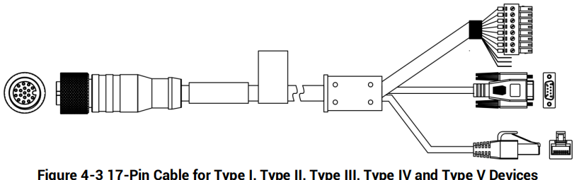
Figure 4-3 17-Pin Cable for Type I, Type II, Type III, Type IV and Type V Devices
Figure description (text version): Cable drawing: 17-pin M12 female connector on the left; the cable splits into three ends – an 8-pin terminal block, a DB9 female serial port connector and an RJ45 Ethernet connector.
The 8-pin terminal is shown below. Refer to table 4-3 for the type I, type II, type III and type IV devices’ pin definitions, and refer to table 4-4 for the type V device’s pin definitions.
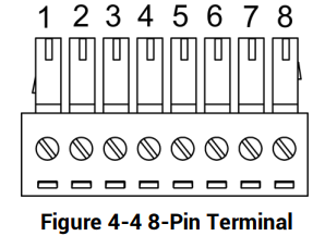
Figure 4-4 8-Pin Terminal
Figure description (text version): Pluggable 8-pin screw terminal block, pins numbered 1 to 8 from left to right.
Table 4-3 8-Pin Terminal Definitions (Type I, Type II, Type III and Type IV Devices)
| No. | Signal | Description | Cable Color |
|---|---|---|---|
| 1 | DO_5 | – | Brown |
| 2 | DO_4 | – | Blue |
| 3 | DO_3 | Non-isolated output | Brown/White |
| 4 | DI_2 | Non-isolated input | Blue/White |
| 5 | DI_1 | It can be configured as input or output, and is input by default. | White |
| 6 | DI_0 | It can be configured as input or output, and is input by default. | Gray |
| 7 | GND | Direct current power supply negative | Black |
| 8 | POWER_IN | Direct current power supply positive | Red |
Table 4-4 8-Pin Terminal Definitions (Type V Device)
| No. | Signal | Description | Cable Color |
|---|---|---|---|
| 1 | OUT_COM | Output common port | Brown |
| 2 | IN_COM | Input common port | Blue |
| 3 | GPIO3 | Opto-isolated output 1 | Brown/White |
| 4 | GPIO2 | Opto-isolated output 0 | Blue/White |
| 5 | GPIO1 | Opto-isolated input 1 | White |
| 6 | GPIO0 | Opto-isolated input 0 | Gray |
| 7 | GND | Direct current power supply negative | Black |
| 8 | POWER_IN | Direct current power supply positive | Red |
Note: The supplied 17-pin cable may differ by device models.
Type VI Device
Type VI device has a DB15 connector. Refer to the figure and table below for connector pin definitions.
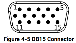
Figure 4-5 DB15 Connector
Figure description (text version): Front view of the DB15 (D-sub, 3 rows) connector: pins 1–5 in the top row, 6–10 in the middle row and 11–15 in the bottom row.
Table 4-5 Pin Definitions (Type VI Device)
| No. | Signal | I/O Signal Source | Description | Supplied Cable |
|---|---|---|---|---|
| 1 | POWER_IN | – | Direct current power supply positive | DB9 male serial port |
| 2 | RS232_TX | – | RS-232 serial port output | DB9 male serial port |
| 3 | RS232_RX | – | RS-232 serial port input | DB9 male serial port |
| 4 | GND | Line 0/1/2/3- | Direct current power supply negative | 6-pin terminal |
| 5 | OPTO_IN0 | LineIn 0+ | Non-isolated input 0 | 6-pin terminal |
| 6 | TX+ | – | Fast Ethernet signal TX+ | RJ45 Ethernet connector |
| 7 | RX- | – | Fast Ethernet signal RX- | RJ45 Ethernet connector |
| 8 | OPTO_OUT | LineOut 2+ | Non-isolated output 2 | 6-pin terminal |
| 9 | Reserved | |||
| 10 | IO_2 | LineOut 3+ | Non-isolated output 3 | 6-pin terminal |
| 11 | Reserved | |||
| 12 | Reserved | |||
| 13 | IO_1 | LineIn 1+ | Non-isolated input 1 | 6-pin terminal |
| 14 | TX- | – | Fast Ethernet signal TX- | RJ45 Ethernet connector |
| 15 | RX+ | – | Fast Ethernet signal RX+ | RJ45 Ethernet connector |
For pins 14 and 15 the source table repeats “TX+” and “RX-” in the description column; the descriptions above follow the signal names.
For type VI device, you should use the supplied cable, as shown below, to wire the device. The cable has a DB9 female serial port that corresponds to 1st, 2nd, and 3rd pins of the device’s DB15 connector, and a 6-pin terminal that corresponds to 4th, 5th, 8th, 10th, and 13th pins of the device’s DB15 connector, and a RJ45 connector that corresponds to 6th, 7th, 14th, and 15th pins of the device’s DB15 connector.
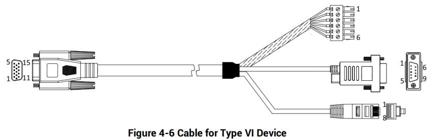
Figure 4-6 Cable for Type VI Device
Figure description (text version): Cable drawing: DB15 connector (pins 1–15) on the left; the cable splits into a 6-pin terminal block (pins 1–6), a DB9 serial port connector (pins 1–9) and an RJ45 Ethernet connector (pins 1–8).
Refer to the figure and table below for the pin definitions of the 6-pin terminal.
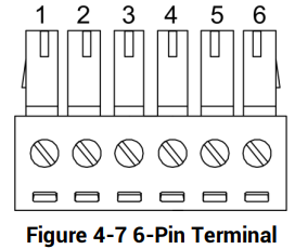
Figure 4-7 6-Pin Terminal
Figure description (text version): Pluggable 6-pin screw terminal block, pins numbered 1 to 6 from left to right.
Table 4-6 Pin Definitions (6-Pin Terminal)
| No. | Signal | Description | Cable Color |
|---|---|---|---|
| 1 | LINEIN 0 | Non-isolated input 0 | Blue |
| 2 | LINEOUT 2 | Non-isolated output 2 | Gray |
| 3 | LINEOUT 3 | Non-isolated output 3 | Brown |
| 4 | LINEIN 1 | Non-isolated input 1 | Purple |
| 5 | GND | Direct current power supply ground | Black |
| 6 | VCC | Direct current power supply positive | Red |
Caution: You cannot use the DB9 female serial port and VCC to power the device at the same time. Otherwise, the power supply may be damaged.
4.2 Device with USB Interface
Device with USB interface includes type I device to type VII device.
Type I to Type V Devices
Type I, type II, type III, type IV and type V devices all have a 17-pin M12 connector. Refer to the figure and table below for connector pin definitions.
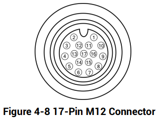
Figure 4-8 17-Pin M12 Connector
Figure description (text version): Front view of the round 17-pin M12 connector: pins 1–11 on the outer ring, pins 12–17 in the inner circle.
Table 4-7 Pin Definitions (Type I to Type V Devices)
| No. | Signal | I/O Signal Source | Description | Supplied Cable |
|---|---|---|---|---|
| 1 | DC_PWR | – | Direct current power supply positive | 8-pin terminal |
| 2 | OUT_COM | LineOut 0/1 signal ground | Output common port | 8-pin terminal |
| 3 | USB_DM | – | USB DM signal | USB interface |
| 4 | RS232TX | – | RS-232 serial port output | DB9 female serial port |
| 5 | RS232RX | – | RS-232 serial port input | DB9 female serial port |
| 6 | Reserved | |||
| 7 | Reserved | |||
| 8 | OPTO_OUT0 | LineOut 0 signal line | Opto-isolated output 0 | 8-pin terminal |
| 9 | IN_COM | LineIn 0/1 signal ground | Input common port | 8-pin terminal |
| 10 | OPTO_OUT1 | LineOut 1 signal line | Opto-isolated output 1 | 8-pin terminal |
| 11 | GND | – | Direct current power supply negative | 8-pin terminal |
| 12 | USB_DP | – | USB DP signal | USB interface |
| 13 | Reserved | |||
| 14 | Reserved | |||
| 15 | Reserved | |||
| 16 | OPTO_IN0 | LineIn 0 signal line | Opto-isolated input 0 | 8-pin terminal |
| 17 | OPTO_IN1 | LineIn 1 signal line | Opto-isolated input 1 | 8-pin terminal |
For type I to type V devices with USB interface, you should use the supplied 17-pin cable below to wire them. The cable has a DB9 female serial port connector that corresponds to 4th and 5th pins of the 17-pin M12 connector, and a USB interface that corresponds to 3th and 12th pins of the 17-pin M12 connector. Others lines of the 17-pin cable have been made into an 8-pin terminal.
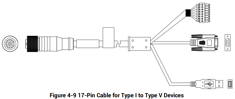
Figure 4-9 17-Pin Cable for Type I to Type V Devices
Figure description (text version): Cable drawing: 17-pin M12 female connector on the left; the cable splits into an 8-pin terminal block, a DB9 female serial port connector and a USB type-A connector.
Refer to the figure and table below for the pin definitions of the 8-pin terminal.
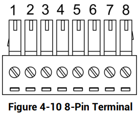
Figure 4-10 8-Pin Terminal
Figure description (text version): Pluggable 8-pin screw terminal block, pins numbered 1 to 8 from left to right.
Table 4-8 8-Pin Terminal Definitions (Type I to Type V Devices)
| No. | Signal | Description | Cable Color |
|---|---|---|---|
| 1 | DO_5 | – | Brown |
| 2 | DO_4 | – | Blue |
| 3 | DO_3 | Non-isolated output | Brown/White |
| 4 | DI_2 | Non-isolated input | Blue/White |
| 5 | DI_1 | It can be configured as input or output, and is input by default. | White |
| 6 | DI_0 | It can be configured as input or output, and is input by default. | Gray |
| 7 | GND | Direct current power supply negative | Black |
| 8 | POWER_IN | Direct current power supply positive | Red |
Note: The supplied 17-pin cable may differ by device models.
Type VI Device
Type VI device has a DB15 connector. Refer to the figure and table below for connector pin definitions.
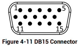
Figure 4-11 DB15 Connector
Figure description (text version): Front view of the DB15 connector: pins 1–5 in the top row, 6–10 in the middle row and 11–15 in the bottom row.
Table 4-9 Pin Definitions (Type VI Device)
| No. | Signal | I/O Signal Source | Description |
|---|---|---|---|
| 4 | GND | – | Direct current power supply negative |
| 9 | POWER_5IVN | – | USB power interface |
| 11 | USB_DM | – | USB 2.0 signal negative |
| 12 | USB_DP | – | USB 2.0 signal positive |
For type VI device, you should use the supplied cable, as shown below, to wire the device. The cable has a 15-pin connector for connecting with the device, and a USB interface for connecting with the PC.
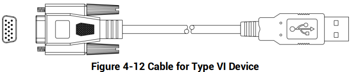
Figure 4-12 Cable for Type VI Device
Figure description (text version): Cable drawing: DB15 connector with screw locks on the left and a USB type-A plug on the right.
Type VII Device
Type VII device with USB interface has a cable with 10-pin RJ45 female connector. It is recommended to use the supplied cable, as shown below, in the package when using the device. The supplied cable has a RJ45 male connector for connecting the device, and a USB interface for connecting external devices.
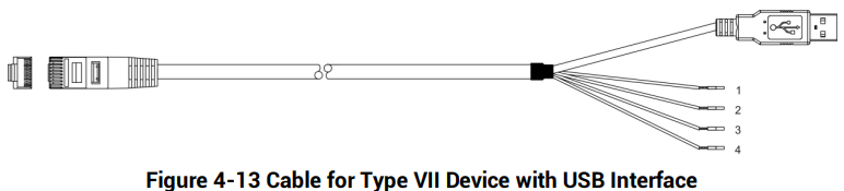
Figure 4-13 Cable for Type VII Device with USB Interface
Figure description (text version): Cable drawing: RJ45 male plug on the left; the cable splits into a USB type-A plug and four open lines numbered 1–4 (see Table 4-10).
The supplied cable also has four open lines with different colors, and you can wire them according to actual demands.
Table 4-10 Open Line Definitions
| No. | Signal | I/O Signal Source | Description | Color |
|---|---|---|---|---|
| 1 | OPTO_OUT0 | LineOut 3 | Non-isolated output | Brown |
| 2 | OPTO_IN0 | LineIn 1 | Non-isolated input | Yellow |
| 3 | GPIO1 | Line 2 | It can be configured as input or output via the client software. | Orange |
| 4 | GND | – | Direct current power supply ground | Black |
4.3 Device with RS-232 Interface
Type VII device with RS-232 interface has a cable with 10-pin RJ45 female connector. It is recommended to use the supplied cable, as shown below, in the package when using the device. The supplied cable has a RJ45 male connector for connecting the device, and a DB9 interface for connecting external devices.
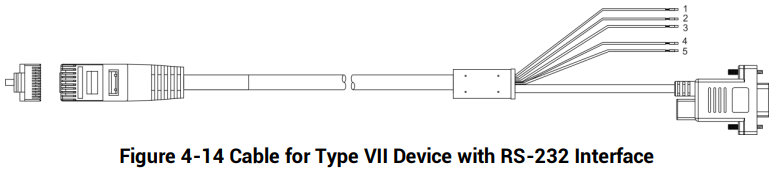
Figure 4-14 Cable for Type VII Device with RS-232 Interface
Figure description (text version): Cable drawing: RJ45 male plug on the left; the cable splits into a DB9 serial connector and five open lines numbered 1–5 (see Table 4-11).
The supplied cable also has five open lines with different colors, and you can wire them according to actual demands.
Table 4-11 Open Line Definitions
| No. | Signal | I/O Signal Source | Description | Color |
|---|---|---|---|---|
| 1 | OPTO_OUT0 | LineOut 3 | Non-isolated output | Brown |
| 2 | OPTO_IN0 | LineIn 1 | Non-isolated input | Orange |
| 3 | GPIO1 | Line 2 | It can be configured as input or output via the client software. | Yellow |
| 4 | VCC | – | Direct current power supply positive | Red |
| 5 | GND | – | Direct current power supply ground | Black |
Caution: You cannot use the DB9 serial port and VCC to power the device at the same time. Otherwise, the power supply may be damaged.
4.4 IO Box
You can use IO box to connect NPN/PNP devices to access to pull-up and pull-down resistors.
- ID2000 series industrial code reader: You should use the supplied cable to connect the code reader to the top terminal of the IO box.
- External devices: You should connect external devices to the bottom terminal of the IO box.
- Pull-up and pull-down resistors: if the DIP switch is switched to DOWN, pull-down resistor is connected. If the DIP switch is switched to UP, pull-up resistor is connected.
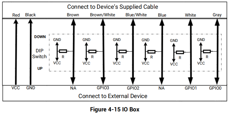
Figure 4-15 IO Box
Figure description (text version): Top terminal (connect to the device’s supplied cable), wire colours from left: Red, Black, Brown, Brown/White, Blue/White, Blue, White, Gray. Bottom terminal (connect to external device): VCC, GND, NA, GPIO3, GPIO2, NA, GPIO1, GPIO0. Each of the six signal lines has a resistor R that a DIP switch connects to GND (switch DOWN – pull-down) or to VCC (switch UP – pull-up).
Note: The IO box may not be included in the package due to different device models.
Słowa kluczowe
Hikrobot ID2000, connector, cable, 17-pin M12, DB15, pinout, pin definitions, 8-pin terminal, 6-pin terminal, cable color, RJ45, DB9, USB, RS-232, open line, IO box, DIP switch, pull-up, pull-down
No comments to display
No comments to display