
3. Appearance
Streszczenie: Wygląd siedmiu typów czytnika ID2000 (I–VII: obiektyw zmiennoogniskowy, z pokrętłem ostrości, C-mount, stałoogniskowe, kompaktowy) oraz opis elementów: przycisk wyzwalania/Smart Tune, kabel SR, wskaźniki LNK, statusu i PWR, oświetlenie, sensor, celownik, mocowanie obiektywu i brzęczyk.
EN: Appearance of the seven ID2000 types (I–VII: vari-focal, focus knob, C-mount, fixed-focal, compact) and component description: trigger/smart tune button, SR cable, LNK, status and PWR indicators, light source, sensor, aiming light, lens mount and buzzer.
Dotyczy: przemysłowy czytnik kodów Hikrobot serii ID2000 (typy I–VII; Fast Ethernet, USB lub RS-232; obsługa przez klienta IDMVS i kody konfiguracyjne)
Źródło: dokumentacja producenta (Hikrobot ID2000 Series Industrial Code Reader User Manual); tabele i uwagi przepisane z obrazów na tekst; opisy rysunków – opracowanie Multiprojekt
Note: Appearance here is for reference only. Refer to the device’s specification for detailed dimension information.
Device Types
Refer to the table and figures below for the information and appearance of different device models.
Table 3-1 Device Description
| Figure | Device Description |
|---|---|
| Figure 3-1, Type I Device | The device does not have a focus knob, but it supports adjusting focus via its solid vari-focal lens. |
| Figure 3-2, Type II Device | The device is a vari-focal device that supports adjusting focus manually via its focus knob. Its focal length is short. |
| Figure 3-3, Type III Device | The device is a vari-focal device that supports adjusting focus manually via its focus knob. Its focal length is long. |
| Figure 3-4, Type IV Device | The device has a C-mount lens mount. |
| Figure 3-5, Type V Device | The device is a fixed-focal device whose focus cannot be adjusted. |
| Figure 3-6, Type VI Device | The device is a fixed-focal device whose focus cannot be adjusted. |
| Figure 3-7, Type VII Device | The device is a fixed-focal device whose focus cannot be adjusted. It adopts compact design and is small in size. |
Appearance Drawings
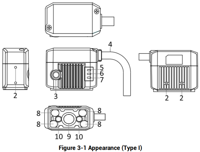
Figure 3-1 Appearance (Type I)
Figure description (text version): Technical drawing in five views (top, left, front, right, bottom). Callouts: 2 – screw holes, 3 – button, 4 – SR cable, 5 – LNK indicator, 6 – status indicator, 7 – PWR indicator, 8 – light source, 9 – sensor, 10 – aiming light. No focus knob. See Table 3-1 Component Description.
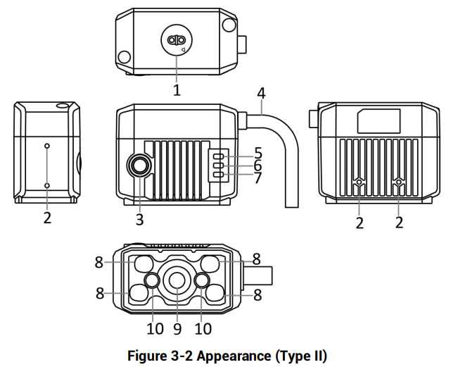
Figure 3-2 Appearance (Type II)
Figure description (text version): Technical drawing in five views. Callouts: 1 – focus knob (on top), 2 – screw holes, 3 – button, 4 – SR cable, 5–7 – LNK, status and PWR indicators, 8 – light source, 9 – sensor, 10 – aiming light.
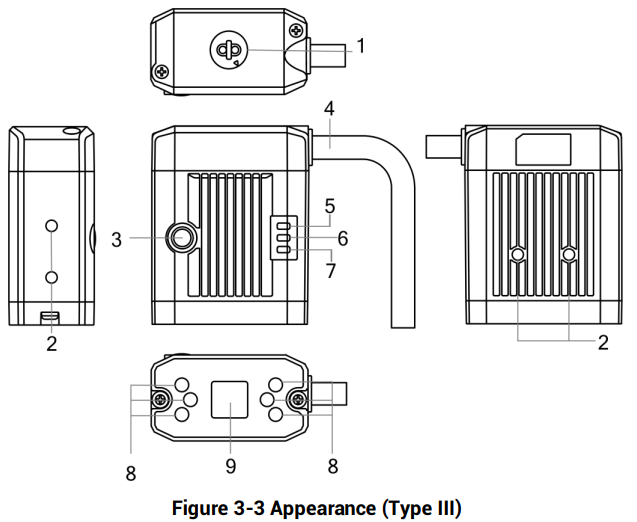
Figure 3-3 Appearance (Type III)
Figure description (text version): Technical drawing in five views. Callouts: 1 – focus knob (on top), 2 – screw holes, 3 – button, 4 – SR cable, 5–7 – LNK, status and PWR indicators, 8 – light source, 9 – sensor.
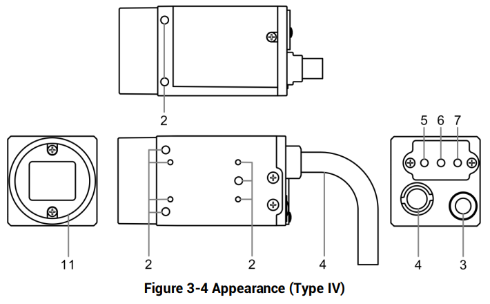
Figure 3-4 Appearance (Type IV)
Figure description (text version): Technical drawing of the C-mount device (front, top, side and rear views). Callouts: 2 – screw holes, 3 – button, 4 – SR cable, 5–7 – LNK, status and PWR indicators on the rear, 11 – lens mount.
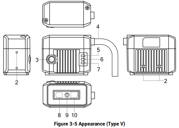
Figure 3-5 Appearance (Type V)
Figure description (text version): Technical drawing in five views. Callouts: 2 – screw holes, 3 – button, 4 – SR cable, 5–7 – LNK, status and PWR indicators, 8 – light source, 9 – sensor, 10 – aiming light (fixed-focal device).
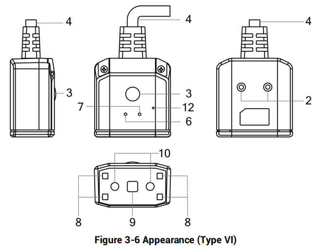
Figure 3-6 Appearance (Type VI)
Figure description (text version): Technical drawing of the device with the cable on top. Callouts: 2 – screw holes, 3 – button, 4 – SR cable, 6 – status indicator, 7 – PWR indicator, 8 – light source, 9 – sensor, 10 – aiming light, 12 – buzzer. No LNK indicator.
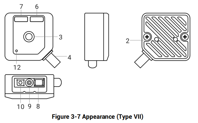
Figure 3-7 Appearance (Type VII)
Figure description (text version): Technical drawing of the compact device (front, side, rear and bottom views). Callouts: 2 – screw holes, 3 – button, 4 – SR cable, 6 – status indicator, 7 – PWR indicator, 8 – light source, 9 – sensor, 10 – aiming light, 12 – buzzer. No LNK indicator.
Component Description
Table 3-1 Component Description
| No. | Name | Description |
|---|---|---|
| 1 | Focus Knob | It is used to adjust focal length manually. |
| 2 | Screw Hole | It is used to fix the device to the installation position. |
| 3 | Button | It is used to trigger the device or execute the smart tune process. • Trigger button: when the device is in trigger mode, press the button and the device triggers once. • Smart tune button: hold the button for 3 s and the device starts smart tune. Hold the button for 3 s again during the smart tune process, and the adjustment will be cancelled. Note: The specific function of the button may differ by device models. |
| 4 | SR Cable | The SR cable connector provides power, I/O, Ethernet, and serial port. Note: The specific function of the SR cable may differ by device models. |
| 5 | LNK Indicator | It is a network status indicator. The indicator is flashing green when the network transmission is normal. Otherwise, it is unlit. Note: Type VI and type VII devices do not have a LNK indicator. |
| 6 | Status Indicator | • It is red when the device starts up or an operation error occurs. • It is unlit when the device operates normally without reading codes. • It is green for 0.5 s when the device reads codes successfully, solid green when the device reads codes continuously, and red when the device does not read codes. Note: The specific function of the status indicator may differ by device models. |
| 7 | PWR Indicator | It is a power indicator. The indicator is red during the device’s power-on process. After the device is powered on, the indicator is green. |
| 8 | Light Source | It is the LED light source used to provide light when the device acquires images. Note: The light source color differs by device models. |
| 9 | Sensor | It is used to acquire images. |
| 10 | Aiming Light | It helps to indicate the field of view and aim targets. |
| 11 | Lens Mount | It is used to install the lens. |
| 12 | Buzzer | The buzzer beeps three times when the device is powered on, beeps twice when the device reads setting codes successfully, and beeps once when the device reads codes successfully. Note: Only type VI and type VII devices have a buzzer. |
Słowa kluczowe
Hikrobot ID2000, appearance, wygląd, Type I, Type II, Type III, Type IV, Type V, Type VI, Type VII, focus knob, C-mount, button, smart tune, SR cable, LNK, PWR, status indicator, aiming light, buzzer
No comments to display
No comments to display