
9. Device Settings – Part 1 (Feature Tree, Reading Mode, Image Quality)
Streszczenie: Ustawienia ID2000 cz. 1: drzewo funkcji, tryb odczytu (dokładny/wsadowy), parametry obrazu, polling (single/multiple), oświetlenie i celownik, Smart Tune, ostrość (auto, ręczna, ROI), samoczynne dopasowanie i obraz testowy.
EN: ID2000 settings part 1: feature tree, code reading mode (accurate/batch), image parameters, polling, light source and aiming, smart tune, focus (auto, manual, ROI), self-adaptive adjustment and test pattern.
Dotyczy: przemysłowy czytnik kodów Hikrobot serii ID2000 (typy I–VII; Fast Ethernet, USB lub RS-232; obsługa przez klienta IDMVS i kody konfiguracyjne)
Źródło: dokumentacja producenta (Hikrobot ID2000 Series Industrial Code Reader User Manual); tabele i uwagi przepisane z obrazów na tekst; opisy rysunków – opracowanie Multiprojekt
Rozdział 9 „Device Settings” – części: Part 1 – Feature Tree, Reading Mode, Image Quality | Part 2 – Code Algorithm and Line Mode | Part 3 – Signal Input and Output | Part 4 – Communication and Data Processing | Part 5 – Multicast, Contrast, Statistics, Events, User Set
następna część →
9.1 Feature Tree Introduction
After the device is connected to the client software, and you can right click the device in Device Connection, and click Feature Tree.
Note: The parameters of the feature tree may differ by device models and firmware versions.
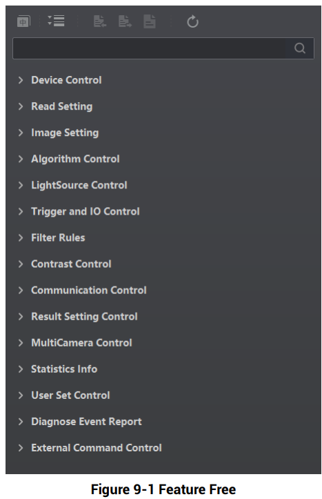
Figure 9-1 Feature Tree
Figure description (text version): Feature tree panel with a search field and the parameter groups: Device Control, Read Setting, Image Setting, Algorithm Control, LightSource Control, Trigger and IO Control, Filter Rules, Contrast Control, Communication Control, Result Setting Control, MultiCamera Control, Statistics Info, User Set Control, Diagnose Event Report, External Command Control. (The source caption reads “Feature Free”.)
Table 9-1 Feature Tree Description
| Name | Description |
|---|---|
| Device Control | It allows you to view the device’s information, edit its name, etc. |
| Read Setting | It allows you to set the device’s operation mode and select code types. |
| Image Setting | It allows you to set frame rate, exposure, gain, Gamma, etc. |
| Algorithm Control | It allows you to set algorithm parameters. |
| Focus Control | It allows you to set the device’s focus mode and related parameters. |
| Self Adapt Control | It allows the device to automatically adjust exposure, gain, Gamma and other parameters to have a better code reading effect. |
| Light Source Control | It allows you to set the light source’s parameters. |
| Line Mode Control | It allows you to customize the specific line as input or output according to actual demands. |
| Trigger and IO Control | It allows you to set parameters of input and output. |
| Stop Trigger Control | It allows you to stop device trigger via TCP, UDP, I/O, serial port and USB. You can also set the code reading timeout duration or the max. code amount to be read to stop trigger. |
| Filter Rules | It allows you to set the filter rule of codes. |
| Communication Control | It allows you to set parameters related to different communication protocols. |
| Multi Camera Control | It allows you to set parameters of multi-camera to let them operate in a collaborative way. |
| Result Setting Control | It allows you to set parameters of outputted contents. |
| Statistics Info. | It allows you to count data related to code reading. |
| User Set Control | It allows you to save and load configured user sets. |
| Diagnose Event Report | It allows you to monitor memory and CPU usage rate, and lets you know when there is a crash, higher CPU usage rate, insufficient memory, etc. |
9.2 Code Reading Mode Settings
The device supports different code reading modes, including accurate mode and batch mode.
Steps
- Right click the device in Device Connection, and click Feature Tree.
- Go to Trigger and IO Control → Accurate Mode Enable, and enable Accurate Mode Enable.
Note: Enabling Accurate Mode Enable is accurate mode, and disabling it is batch mode.
Table 9-2 Parameters Description
| Code Reading Mode | Description |
|---|---|
| Accurate Mode | It reads codes containing the cross laser center in the code area only. The code reading process ends if codes are read successfully or the trigger switch is released. |
| Batch Mode | It can read multiple codes when the trigger switch is pressed. After code reading is finished, the result will be packaged and outputted. The code reading process ends if the expected code quantity is reached or exceeded, code reading timed out, the valid frame quantity is reached, or the trigger switch is released. |
Note: The function of code reading mode may differ by device models.
9.3 Image Quality Settings
This section introduces how to set image related parameters of the device via client software.
Note: For different models of the device, the specific parameters may differ, and the actual device you purchased shall prevail.
9.3.1 Set Image
You can set parameters like exposure time, gain, Gamma, acquisition frame rate, acquisition burst frame count, etc. in Image Settings area.
Table 9-3 Set Image Parameters
| Name | Description |
|---|---|
| Exposure Time | You can increase exposure time to improve image brightness. Note: To some extent, increasing exposure time will reduce acquisition frame rate, and impact image quality. |
| Gain | You can increase gain to improve image brightness. Note (as in the source): To some extent, increasing exposure time will reduce acquisition frame rate, and affect image quality. |
| Gamma | Gamma allows you to adjust the image contrast. It is recommended to reduce Gamma to increase brightness in dark background. |
| Acquisition Frame Rate | Acquisition frame rate refers to the image number that is acquired by the device per second. |
| Acquisition Burst Frame Count | Acquisition burst frame count refers to the outputted image number when the device is triggered once. |
| Polling Enable | It enables the polling function; you can select off, single or multiple mode. Note: The parameter of polling enable will be displayed only when the trigger mode is on. |
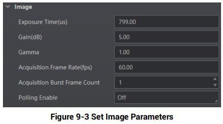
Figure 9-3 Set Image Parameters
Figure description (text version): Image parameter group: Exposure Time (us) 799.00, Gain (dB) 5.00, Gamma 1.00, Acquisition Frame Rate (fps) 60.00, Acquisition Burst Frame Count 1, Polling Enable Off.
9.3.2 Set Polling
The polling function allows the device to acquire images based on the parameters you set, including exposure time, gain, Gamma, light source, focus position, etc. Currently, two types of polling modes are available, including single mode and multiple mode.
Note:
- Stopping the real-time acquisition is required before setting the polling function.
- After polling is enabled, the device acquires images with its max. frame rate. Once polling is disabled, the frame rate you set in Acquisition Frame Rate takes effect.
- The polling function and specific parameters may differ by device models.
- It is recommended to use the polling function in the normal operation mode; test/raw modes are used for debugging only.
- The specific parameters of polling may differ by device models.
Single Mode
Steps
- Right click the device in Device Connection, and click Feature Tree.
- Go to Image Setting → Polling Mode, and select Single as Polling Enable.
- Select one parameter (e.g. Param1) from Polling Param.
Note: Up to 8 sets of parameters can be selected from Polling Param.
- Set parameters participating the polling like Polling Exposure Time, Polling Gain, Polling Gamma, etc. according to actual demands.
Table 9-4 Parameters of Single Mode Polling
| Parameter | Description |
|---|---|
| Polling Exposure Time | It sets the exposure time of polling. |
| Polling Gain | It sets the polling gain. |
| Polling Gamma | It sets the polling Gamma value. • If the value is between 0 and 1, the image brightness increases and the dark area becomes brighter. • If the value is between 1 and 4, the image brightness decreases and the dark area becomes darker. |
| Polling Focus Enable | After enabling this parameter, you can set the polling focus position. |
| Polling Focus Position | It sets the polling focus position. |
| Polling Lighting Selector | It selects lamps in different directions, including up/down and mid. |
| Polling Lighting Enable | After enabling this parameter, the light source will turn on. |
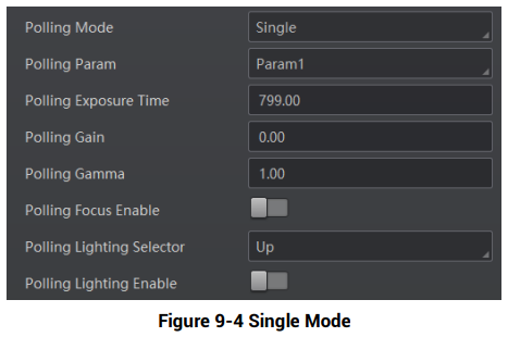
Figure 9-4 Single Mode
Figure description (text version): Polling parameters in single mode: Polling Mode Single, Polling Param Param1, Polling Exposure Time 799.00, Polling Gain 0.00, Polling Gamma 1.00, Polling Focus Enable off, Polling Lighting Selector Up, Polling Lighting Enable off.
Multiple Mode
Note:
- In multiple mode, the device supports trigger parameters like software trigger, external trigger, etc., but does not support stopping polling via the external trigger.
- The rule for multiple-mode polling is that polling is started from the polling parameter with Best Polling Group Idx, and then the other polling parameters you selected are executed in turn. For example, if Param3 is the Best Polling Group Idx and Param1, Param2, Param4 and Param5 are enabled, the polling order is Param3 > Param1 > Param2 > Param4 > Param5.
Steps
- Right click the device in Device Connection, and click Feature Tree.
- Go to Image Setting → Polling Mode, and select Multiple as Polling Enable.
- Set Polling Time and Polling Period according to actual demands.
- Polling Time is used to determine whether the polling is finished or not, and it ranges from 100 to 2147482.
- Polling Period is whole period from Param1 to Param8, and it ranges from 1 to 5000.
- Select 2 to 8 sets of parameters (e.g. Param1 and Param2) from Polling Param, and enable Polling Param Enable to let them take effect.
- Set parameters participating the polling like Polling Exposure Time, Polling Gain, Polling Gamma, etc. according to actual demands.
Table 9-5 Parameters of Multiple Mode Polling
| Parameter | Description |
|---|---|
| Polling Exposure Time | It sets the exposure time of polling. |
| Polling Gain | It sets the polling gain. |
| Polling Gamma | It sets the polling Gamma value. • If the value is between 0 and 1, the image brightness increases and the dark area becomes brighter. • If the value is between 1 and 4, the image brightness decreases and the dark area becomes darker. |
| Polling Focus Enable | After enabling this parameter, you can set the polling focus position. |
| Polling Focus Position | It sets the polling focus position. |
| Polling Lighting Selector | It selects lamps in different directions, including up/down and mid. |
| Polling Lighting Enable | After enabling this parameter, the light source will turn on. |
- Repeat step 4 and step 5 to set other parameters from Polling Param.
- (Optional) View Polling Status and Best Polling Group Idx.
- Polling Status: It displays the current polling status. 0 stands for polling ended, and 1 stands for polling started.
- Best Polling Group Idx: It is used to display the polling parameter number when the device recognizes codes after enabling polling. If the polling is disabled or polling parameters are edited, it displays 1 by default.
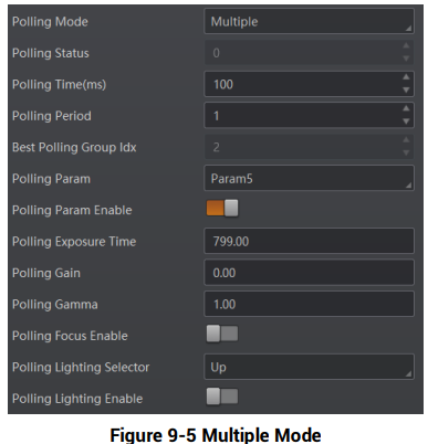
Figure 9-5 Multiple Mode
Figure description (text version): Polling parameters in multiple mode: Polling Mode Multiple, Polling Status 0, Polling Time (ms) 100, Polling Period 1, Best Polling Group Idx 1, Polling Param Param1, Polling Param Enable on, Polling Exposure Time 799.00, Polling Gain 0.00, Polling Gamma 1.00, Polling Focus Enable off, Polling Lighting Selector Up, Polling Lighting Enable off.
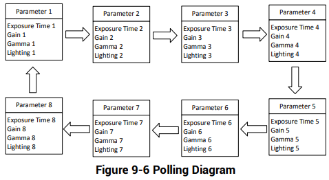
Figure 9-6 Polling Diagram
Figure description (text version): Diagram of eight parameter sets (each with its own exposure time, gain, Gamma and lighting) executed in a loop: Parameter 1 → 2 → 3 → 4 in the top row, then Parameter 5 → 6 → 7 → 8 in the bottom row, and back to Parameter 1.
9.3.3 Set Light Source
Light source control allows you to enable the device’s aiming system and light source, and set related parameters according to actual demands.
Note:
- Light source parameters may differ by device models.
- Make sure you have selected the device to be set in Device Connection before setting light source parameters.
Type I Device to Type VI Device
Steps
- Go to Image Settings → Light, and enable Aiming Light Enable according to actual demands.
- Enable Lighting Enable to enable the light source according to actual demands.
- (Optional) Set Lighting Duration and Precharge Time if Lighting Enable is enabled.
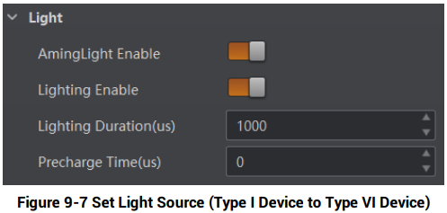
Figure 9-7 Set Light Source (Type I Device to Type VI Device)
Figure description (text version): Light group: AimingLight Enable on, Lighting Enable on, Lighting Duration (us) 1000, Precharge Time (us) 0.
Type VII Device
Steps
- Go to Image Settings → Light, and select Lighting Mode according to actual demands.
- Enable Laser Enable according to actual demands.
- Enable Laser Delay Enable, and enter Laser Delay Duration to delay the close time of the laser after the device stops triggering.
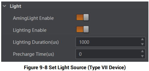
Figure 9-8 Set Light Source (Type VII Device)
Figure description (text version): Light group as shown in the source: AimingLight Enable on, Lighting Enable on, Lighting Duration (us) 1000, Precharge Time (us) 0 (the screenshot is the same as in Figure 9-7).
9.3.4 Set Smart Tune
The smart tune function allows you to adjust the device’s focus position, exposure, gain, etc. by one-key operation, and supports self-adaptive adjustment.
The smart tune function has two methods to be realized, including smart tune by pressing tune button and smart tune via the client software.
Smart Tune by Pressing Tune Button
Note:
- The parameters of the smart tune may differ by device models and firmware versions.
- During the smart tune process, the focus parameters and self-adaptive parameters will be adjusted in turn.
Steps
- Go to Image Settings, click All Features on the right corner, and find Smart Tune Control.
- Enable Button Tune, and disconnect the device from the client software.
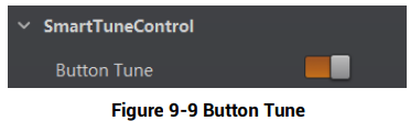
Figure 9-9 Button Tune
Figure description (text version): SmartTuneControl group with the Button Tune switch turned on.
Note: Smart tune by pressing the tune button is not supported if the device is connected via the client software.
Smart Tune via Client Software
Apart from pressing tune button to realize smart tune, you can also configure parameters via the client software to realize it.
Before You Start: Make sure that the device is not in trigger mode, and its operation mode is test.
Steps
- Go to Image Settings, click All Features on the right corner, and find Smart Tune Control.
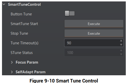
Figure 9-10 Smart Tune Control
Figure description (text version): SmartTuneControl group: Button Tune off, SmartTune Start (Execute), Stop Tune (Execute), Tune Timeout (s) 90, STune Status 100 (read-only), and the collapsed sub-groups Focus Param and SelfAdapt Param.
- (Optional) Set Tune Timeout. If the self-adaptive adjustment exceeds configured value, and it will stop automatically.
- Click Execute in Smart Tune Start to let the device start smart tune, and a window of smart tune will be displayed for you to view the effect.
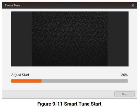
Figure 9-11 Smart Tune Start
Figure description (text version): Smart Tune window: image preview area, status "Adjust Start" with progress 26% and an orange progress bar, Stop button at the bottom right.
- (Optional) View smart tune process via Smart Tune Status.
- Click Execute in Stop Tune to stop smart tune process.
9.3.5 Set Focus
The device supports the focus function according to the code position in the field of view. Currently, three types of focus are supported, including global auto focus, global manual focus, and ROI focus.
Note:
- Make sure that the device’s operation mode is test before performing focus, and switch to the normal operation mode after the focus is completed.
- The focus function may differ by device models.
Global Auto Focus
The global auto focus allows you to adjust lens focus in a global field of view just by once.
Steps
- Go to Image Settings → Smart Tune Control → Focus Param → Focus Mode Selector, and select Whole Area Focus as Focus Mode Selector.
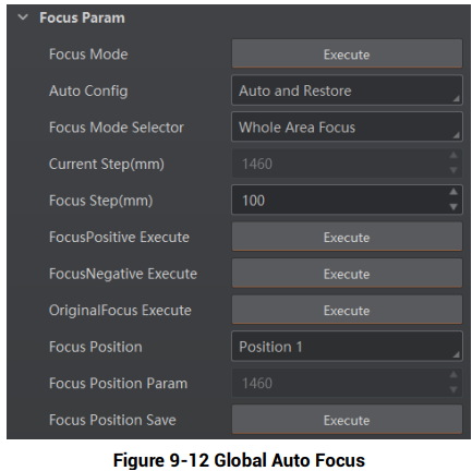
Figure 9-12 Global Auto Focus
Figure description (text version): Focus Param group: Focus Mode (Execute), Auto Config Auto and Restore, Focus Mode Selector Whole Area Focus, Current Step (mm) 1900 (read-only), Focus Step (mm) 100, FocusPositive Execute, FocusNegative Execute, OriginalFocus Execute (Execute buttons), Focus Position Position 1, Focus Position Param 1900, Focus Position Save (Execute).
- Click
 in the live view window, and click it again to stop acquisition and make sure there is an image in the window.
- Select the focus mode in Auto Config:
- Full Auto: In this mode, the device will automatically change parameters like focus position, exposure, gain, Gamma and light source when adjusting focus.
- Motor Only: In this mode, the device will change focus position only when adjusting focus.
- Auto and Restore: In this mode, the device will automatically change parameters like focus position, exposure, gain, Gamma and light source when adjusting focus, and keep focus position and restore other parameters after completing focus adjustment.
- Click Execute in Focus Mode, and the device starts to adjust focus automatically.
- (Optional) Select the position parameter from Focus Position, and click Execute in Focus Position Save to save the focus position after adjusting focus.
Global Manual Focus
The global manual focus requires manual focus according to the images displayed in the live view window.
Steps
- Go to Image Settings → Smart Tune Control → Focus Param → Focus Mode Selector, and select Whole Area Focus as Focus Mode Selector.
- Click in the live view window, and click it again to stop acquisition and make sure there is an image in the window.
- Select Focus Position according to actual demands and Focus Position Param.
- Set Focus Step according to actual demands.
- Click Execute in Focus Positive Execute and Focus Negative Execute to adjust focus position.
- (Optional) View Focus Score to know the score of the focus adjustment.
- (Optional) Select the position parameter from Focus Position, and click Execute in Focus Position Save to save the focus position after adjusting focus.
- (Optional) Click Execute in Original Focus Execute to let the focus back to its original position.
ROI Focus
The ROI focus allows you to adjust lens focus regarding the ROI area by drawing specific area.
Note: The ROI focus is applicable to scenarios where multiple codes with different depths of field exist.
Steps
- Go to Image Settings → Smart Tune Control → Focus Param → Focus Mode Selector, and select ROI Area Focus as Focus Mode Selector.
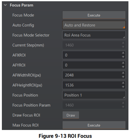
Figure 9-13 ROI Focus
Figure description (text version): Focus Param group: Focus Mode (Execute), Auto Config Auto and Restore, Focus Mode Selector ROI Area Focus, Current Step (mm) 1900, AFXROI 0, AFYROI 0, AFWidthROI (px) 2048, AFHeightROI (px) 1536, Focus Position Position 1, Focus Position Param 1900, Draw Focus ROI (Draw), Max Focus ROI (Execute).
- Click
 in the live view window, and click it again to stop acquisition and make sure there is image in the window.
- Click Draw in Draw Focus ROI, and draw ROI by dragging the mouse in live view window.
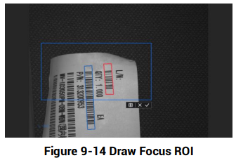
Figure 9-14 Draw Focus ROI
Figure description (text version): Live view image of a label with several codes; a blue rectangular focus ROI is drawn over part of the label.
- (Optional) Set following parameters to adjust ROI size and position.
- AF Offsex X: It is X coordinate of the upper left corner in ROI where executes auto focus.
- AF Offsex Y: It is Y coordinate of the upper left corner in ROI where executes auto focus.
- AF Width ROI: It refers to the width in ROI where executes auto focus.
- AF Height ROI: It refers to the height in ROI where executes auto focus.
- (Optional) Click Execute in Max. Focus ROI to have a global focus.
- (Optional) Repeat step 3 if you want to set multiple ROIs.
9.3.6 Set Self-Adaptive Adjustment
The function of self-adaptive adjustment can automatically adjust exposure, gain, Gamma and other parameters to have a better code reading effect.
Note: The function of self-adaptive adjustment may differ by device models.
Steps
- Go to Image Settings → Smart Tune Control → Self Adapt Adjust, and unfold Self Adapt Adjust.
- Select Adjust Source according to actual demands.
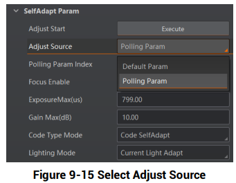
Figure 9-15 Select Adjust Source
Figure description (text version): SelfAdapt Param group: Adjust Start (Execute), Adjust Source drop-down opened with Default Param and Polling Param, Polling Param Index, Focus Enable, ExposureMax (us) 799.00, Gain Max (dB) 10.00, Code Type Mode Code SelfAdapt, Lighting Mode Current Light Adapt.
- Default Param: It adjusts the default parameters.
- Polling Param: It adjusts parameters configured in polling. After Polling Param is selected as Adjust Source, you should select a polling parameter group from Polling Param and enable or disable Focus Enable.
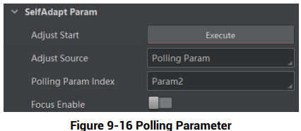
Figure 9-16 Polling Parameter
Figure description (text version): SelfAdapt Param group: Adjust Start (Execute), Adjust Source Polling Param, Polling Param Index Param2, Focus Enable off.
- Set Exposure Max or Gain Max according to actual demands.
- Exposure Max: It sets the max. exposure during the self-adaptive adjustment.
- Gain Max: It sets the max. gain during the self-adaptive adjustment.
- (Optional) Set self-adaptive code type in Code Type Mode.
- Code Self-Adaptive: All code types added in field of view will be self-adaptive.
- 1D Code: 1D code types added in field of view will be self-adaptive.
- 2D Code: 2D code types added in field of view will be self-adaptive.
- Stacked Code: Stacked code types added in field of view will be self-adaptive.
- (Optional) Set light source parameters in Lighting Mode.
- Light Adapt: The client software will select the best one from all lighting options during the self-adaptive adjustment.
- Current Light Adapt: The client software will use the current configured light source.
- All Light Disable: All light sources will be turned off during self-adaptive adjustment process.
- Click Execute in Adjust Start. The device will automatically acquire images and perform self-adaptive adjustment, and stop acquisition after adjustment is completed.
Note: If the adjustment is completed, the client software displays the spent time and prompts that the adjustment succeeded. If the adjustment failed or timed out, the client software prompts adjustment failure or timeout.
9.3.7 Set Test Pattern
Test pattern helps troubleshooting image problems and images in the test pattern are only for test. When exceptions occur in images acquired by the device in real time, you can check if images in the test pattern have similar problems to determine the cause of an exception.
Note:
- The test pattern is available in the test or raw operation mode.
- Specific parameters of this function may differ by device models.
Go to Image Settings, click All Features, find Test Pattern in Other Features, and set Test Pattern according to actual demands.
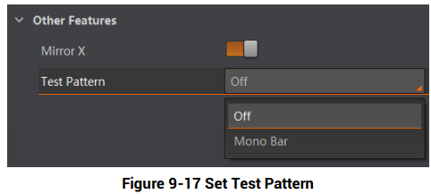
Figure 9-17 Set Test Pattern
Figure description (text version): Other Features group: Mirror X switched on, Test Pattern drop-down opened with the options Off (selected) and Mono Bar.
Słowa kluczowe
Hikrobot ID2000, feature tree, accurate mode, batch mode, exposure, gain, Gamma, polling, light source, aiming light, laser, smart tune, tune button, focus, auto focus, ROI focus, self-adaptive adjustment, test pattern
No comments to display
No comments to display