
9. Device Settings – Part 2 (Code Algorithm and Line Mode)
…Streszczenie: Ustawienia ID2000 cz. 2: dodawanie kodów 1D/2D/stosowych, obszary ROI (pojedyncze i szachownica), parametry algorytmów 1D, 2D i kodów stosowych, ocena jakości kodów 1D (ISO 15416) i 2D (ISO 15415/29158), Code Score oraz tryb linii (wejście/wyjście).
EN: ID2000 settings part 2: adding 1D/2D/stacked codes, ROI (single and chessboard), 1D/2D/stacked algorithm parameters, 1D (ISO 15416) and 2D (ISO 15415/29158) code quality evaluation, code score and line mode.
Dotyczy: przemysłowy czytnik kodów Hikrobot serii ID2000 (typy I–VII; Fast Ethernet, USB lub RS-232; obsługa przez klienta IDMVS i kody konfiguracyjne)
Źródło: dokumentacja producenta (Hikrobot ID2000 Series Industrial Code Reader User Manual); tabele i uwagi przepisane z obrazów na tekst; opisy rysunków – opracowanie Multiprojekt
Rozdział 9 „Device Settings” – części: Part 1 – Feature Tree, Reading Mode, Image Quality | Part 2 – Code Algorithm and Line Mode | Part 3 – Signal Input and Output | Part 4 – Communication and Data Processing | Part 5 – Multicast, Contrast, Statistics, Events, User Set
← poprzednia część · następna część →
9.4 Code Algorithm Settings
The code reader supports reading multiple types of 1D code, 2D code, and stacked codes, and you can add and set code parameters via the client software.
9.4.1 Add Code
Adding code before you set code parameters via the client software. In Algorithm Settings, you can add different types of codes according to actual demands.
In Algorithm Settings, click Add Barcode, select types of codes to be read, and set the 1D Code Number, 2D Code Number, and Stack Bar Number according to actual demands.
Note:
- For different models of the device, the specific parameters may differ, and the actual device you purchased shall prevail.
- The selected symbology amount and added code amount may affect the code recognition time. Selecting more symbologies or adding more codes may consume more time to recognize codes in the image.
- No matter 1D code, 2D code or stacked code number, up to 20 codes can be added at a time. Adding more codes may consume more time to recognize codes in the image. Therefore, the code number should be set according to actual demands.
- The code reader may output the actual code number when there is a mismatch between the actual code number and the code number set in the client software.
9.4.2 Set Code Reading ROI
Algorithm ROI (Region of Interest) allows the device to execute algorithms and read codes on the specific area you selected, and thus improving code reading efficiency.
Currently, multiple ROIs can be configured, and the device outputs codes according to the number of ROI (e.g. Region 1, Region 2, and Region 3…) in turn. The client software supports drawing single group of ROI and drawing ROI via chessboard.
Note:
- If no code is recognized in the algorithm ROI, the device will output “noread”.
- Before drawing ROIs, make sure that there are images in the live view window after stopping preview.
- If no algorithm ROI is enabled, the full screen is the algorithm ROI by default.
- This function may differ by device models.
Draw Single Group of ROI
Steps
- Go to Algorithm Settings, and find Algorithm ROI.
- Click Draw in Draw ROI to draw ROI in the live view window.
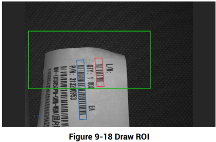
Figure 9-18 Draw ROI
Figure description (text version): Live view image of a label with several codes; a green rectangular algorithm ROI is drawn around the area to be read, the recognized codes are outlined in colour.
- (Optional) Repeat the above step to draw multiple ROIs according to actual demands.
Note: The client software only parses codes in the ROI you drew.
- (Optional) Set other ROI parameters according to actual demands.
- ROI Index: It indicates different ROIs and ranges from 0 to 149 corresponds 1 to 150 ROIs.
- Algo Region Left X: It refers to the X coordinate of the upper left corner in algorithm ROI.
- Algo Region Left Y: It refers to the Y coordinate of the upper left corner in algorithm ROI.
- Algo Region Width: It refers to the width in algorithm ROI.
- Algo Region Height: It refers to the height in algorithm ROI.
- (Optional) Click Execute in Restore Max. Algorithm ROI to restore the ROI to the full screen.
- (Optional) Click Execute in Clear All ROI to delete all ROIs.
Draw ROI via Chessboard
Steps
- Go to Algorithm Settings, and find Algorithm ROI.
- Click Execute in Chessboard ROI, set parameters, and click OK after setting.
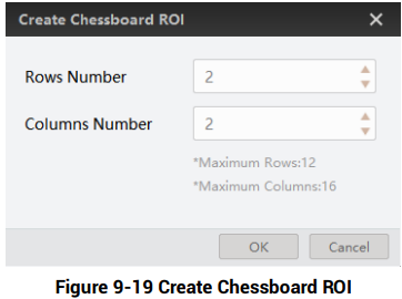
Figure 9-19 Create Chessboard ROI
Figure description (text version): Create Chessboard ROI dialog: Rows Number 2, Columns Number 2 (maximum rows 12, maximum columns 16); OK and Cancel buttons.
- Click the confirm (check mark) icon after creating the ROI, and the red frame becomes green as shown below.
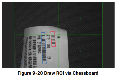
Figure 9-20 Draw ROI via Chessboard
Figure description (text version): Live view image of a label with codes divided by a green grid of chessboard ROIs after confirming (the frames turn from red to green).
- (Optional) Click
 to restore the ROI to full screen, and click
 to clean all ROIs.
- Repeat other optional steps mentioned in drawing single group of ROI.
Note: The figures above are for reference only; refer to the actual conditions.
9.4.3 Set Algorithm Parameter
In Algorithm Parameter, select 1DCode, 2DCode or Stacked Code as Arithmetic Type, and then you can set its corresponding parameters.
Note:
- You should have selected at least one type of 1D code, 2D code or stacked code.
- For different models of the device, the specific parameters may differ, and the actual device you purchased shall prevail.
Set 1D Code
- Timeout Value: Timeout value refers to the maximum running time of algorithm, and its unit is ms. The code reader will stop parsing the images and return results if the time is exceeded the waiting time configured.
- Code Color: It defines the readable code color. White Code On Black Wall means that the client software can recognize the white code with black background. Black Code On White Wall means that the client software can recognize the black code with white background. Adaptive means that the client software can recognize both the black code with white background, and the white code with black background.
- Code 39 Check: Enable this parameter if Code 39 uses the parity bit.
Note: You need to select Code 39 in Add Barcode.
- ITF 25 Check: Enable this parameter if ITF 25 uses the parity bit
Note: You need to select ITF 25 in Add Barcode.
- 1D Code Quality Enable: If it is enabled, the client software will judge the quality of 1D code and output overall grade. Currently, this parameter is only applicable to Code 39 and Code 128.
- Code Score Enable: If it is enabled, the client software will evaluate the code reading environment for 1D code and output code score.
Set 2D Code
- Timeout Value: Timeout value refers to the maximum running time of algorithm, and its unit is ms. The code reader will stop parsing the images and return results if the time is exceeded the waiting time configured.
- Algorithm Running Mode: It is used to be set the algorithm operating mode. It includes High Speed, High Performance, and Balance. High Speed focuses on recognition speed, and the algorithm can recognize the code rapidly, while High Performance refers to the algorithm can recognize the code that has distortion, spot or white gap, but its recognition speed is slow. Balance refers to the algorithm makes a balance between speed and performance.
- 2D Code Max. Size: It refers to the max. recognizable code width. The 2D code will not be recognized if its width exceeds the configured value.
- Mirror Mode: It is useful when the recognized image is a mirror one, mirroring in X coordinate. 3 modes are available: Adaptive, Mirror, and Non Mirror.
- Downsampling Level: It refers to the pixel sample size that the code reader takes. Increasing this parameter will improve the code reading efficiency at the expense of code recognition rate.
Note: Increasing this parameter value will improve the code reading efficiency at the cost of code recognition rate.
- Code Color: It defines the readable code color. Adaptive means that the client software can recognize both the black code with white background, and the white code with black background. White Code On Black Wall means that the client software can recognize the white code with black background. Black Code On White Wall means that the client software can recognize the black code with white background.
Note:
- For QR code, the code color is determined by the color of the concentric (finder) square on it: a white finder square indicates that the code color is white, and a black finder square indicates that the code color is black.
- For DM code, the code color is determined by the color of its “L”-shaped sides: white “L”-shaped sides indicate that the code color is white, and black “L”-shaped sides indicate that the code color is black.
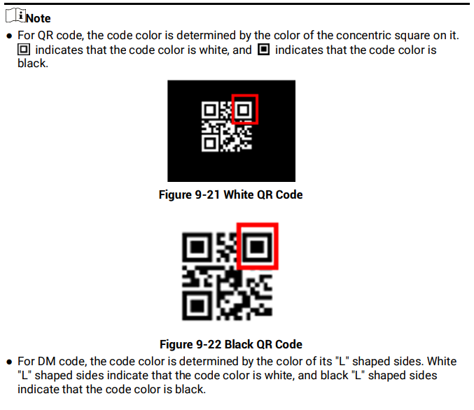
Figure 9-21 White QR Code and Figure 9-22 Black QR Code
Figure description (text version): Two example QR codes with the top-right finder (concentric) square highlighted in red: a white QR code on a black background (Figure 9-21) and a black QR code on a white background (Figure 9-22).
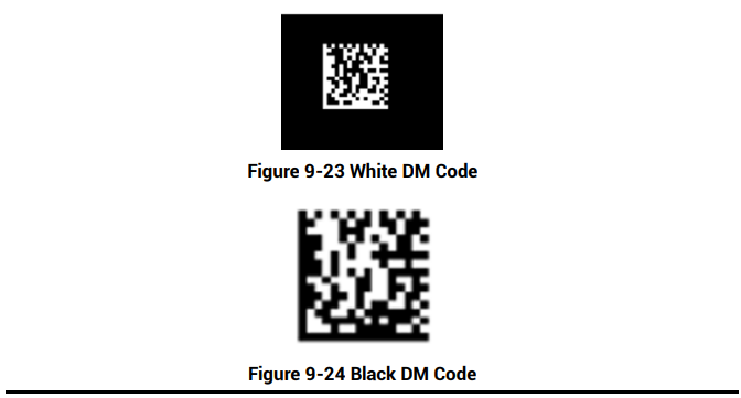
Figure 9-23 White DM Code and Figure 9-24 Black DM Code
Figure description (text version): Two example DataMatrix codes: a white DM code on a black background (Figure 9-23) and a black DM code on a white background (Figure 9-24).
- Discrete Flag: Continuous stands for the minimum units in the "L" shaped sides of the DM code are continuous, or the minimum units in the concentric square like
 or
 in the QR code are continuous. Usually the continuous code uses squares as the minimum units. Discrete stands for the minimum units in the "L" shaped sides of the DM code are discrete, or the minimum units in the concentric square like or in the QR code are discrete. Usually the discrete code uses dots as the minimum units.
Adaptive stands for the device can recognize both continuous code and the discrete code. - QR Distortion Correction: If the QR code or DM code is distorted, you can enable this parameter to improve code recognition rate.
Note: If you enable this parameter, more time will be consumed to recognize the codes in the image.
- DM Code Shape: It defines the recognizable code shape. Square stands for square mode: if the 2D code is square shaped, it can be recognized by the device. Rectangle stands for rectangle mode: If the 2D code is rectangle shaped, it can be recognized by the device.
Adaptive stands for compatible mode: The device can recognize 2D codes of both the above-mentioned two shapes. - DM Code Type: It includes All, ECC140, and ECC200.
- 2D Code Quality Enable: Refer to section Set 2D Code Quality Evaluation for details.
- Code Score Enable: If it is enabled, the device will evaluate code quality and display overall grade and code score in history record area of the client software. The higher the score, and the better the code quality.
- Accurate Timeout Enable: If it is enabled, the accuracy of algorithm timeout will improve.
Set Stacked Code
Code Score Enable: If it is enabled, the client software will evaluate the code reading environment for stacked code and output code score.
9.4.4 Set Code Quality Evaluation
The code quality evaluation function judges the quality of codes and outputs overall grade. Currently, only 1D code and 2D code support code quality evaluation.
Note:
- The function of code quality evaluation may differ by device models.
- In test operation mode, this function is enabled by default. In normal mode, you need to enable it manually.
Set 1D Code Quality Evaluation
The 1D quality evaluation function uses the ISO15416 standard to judges the quality of codes and outputs overall grade. Currently, this function is only applicable to Code 39 and Code 128.
Steps
- Go to Algorithm Control → Algorithm Parameter, and select 1D Code as Arithmetic Type.
- Enable 1D Code Quality Evaluation.
- Enable different quality evaluation standards according to actual demands.
Table 9-6 Quality Evaluation Standards
| Parameter | Description |
|---|---|
| Decodability | It evaluates whether the code has enough basic information to be decoded. |
| Symbol Contrast | It evaluates the difference between the max. brightness value and the min. brightness value of the code area. |
| Modulation | It evaluates the degree of change in terms of brightness. |
| Edge Determination | It evaluates how well the number of edges read by the code matches the configured number of edges. |
| Minimum Reflectance | It evaluates the ratio of the min. brightness value to the max. brightness value. |
| Minimum Edge Contrast | It evaluates the min. value of the reflectivity difference of the strip connecting the spaces. |
| Decode Enable | It evaluates whether the code recognition is successful or not. |
| Defects | It evaluates codes or spaces for defects or dirt. |
| Quiet Zone | It evaluates whether the quiet zone width of the code meets the specification. |
- Set the evaluation value for A/B/C/D grade according to actual demands.
Note:
- If the actual code reading value of the device is greater than the grade A evaluation value, the evaluation standard is grade A. If the actual code reading value is between grade A and grade B, the evaluation standard is grade B. If it is between grade B and grade C, the evaluation standard is grade C. If it is between grade C and grade D, the evaluation standard is grade D. If the actual code reading value is lower than the D grade, the evaluation standard is grade F.
- The client software selects the worst grade among all the evaluation standards as the grade judgment result of the code. Grade A means that the code quality is the best, and grade F means that the code quality is the worst.
- Enable Aperture Enable and enter Aperture according to the smallest size of codes.
- (Optional) Set Quality 1D Max Num to configure the amount of code to be evaluated. If the actual amount of code exceeds the configured, the later codes will not be evaluated.
- (Optional) Go to Algorithm Control → Rating Standard 1D Enable, set enable Rating Standard 1D Enable, and select 1D Rating Standard.
Note: For example, if 1D Rating Standard is C, the client software will output codes with A/B/C grade, and codes with D/F grade will be filtered.
- Click
 to start acquisition, and the client software will display the overall code quality in the history record area.
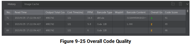
Figure 9-25 Overall Code Quality
Figure description (text version): History panel with columns No., Read Time, Output Total Count, Cost Time (ms), PPM, Barcode Type, Waybill, Barcode Content, Overall Grade and Code Score; three entries (DataMatrix and Code 128) with their overall grades.
Set 2D Code Quality Evaluation
The 2D quality evaluation function uses the ISO15415 standard to judges the quality of codes and outputs overall grade.
Note:
- The specific parameters may differ by device models and firmware versions.
- Make sure that the device’s operation mode is normal and 2D codes are added.
Steps
- Go to Algorithm Control → Algorithm Parameter, and select 2D Code as Arithmetic Type.
- Enable 2D Code Quality Evaluation.
- Set Iso Edition, including Iso15415 and Iso29158
- Iso15415 is applicable to the quality evaluation for label 2-dimensional codes.
- Iso29158 is applicable to the quality evaluation for DPM format 2-dimensional codes.
- Refer to step 5 to step 7 in Set 1D Code Quality Evaluation to set other parameters.
9.4.5 Set Code Score
The code score function evaluates the code-reading environment for codes and outputs code score.
Note:
- The function of code score may differ by device models.
- In test mode, this function is enabled by default. In normal mode, you need to enable it manually.
- The code score is determined by two factors: image quality and print quality of codes. The range of code score is between 0 and 100; the higher the score, the easier the code can be read.
Steps
- Go to Algorithm Settings, and enable Code Score Enable.
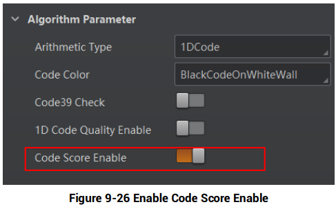
Figure 9-26 Enable Code Score Enable
Figure description (text version): Algorithm Parameter group: Arithmetic Type 1DCode, Code Color BlackCodeOnWhiteWall, Code39 Check off, 1D Code Quality Enable off, Code Score Enable on (highlighted in red).
- Click
 to start acquisition, and the client software will display specific code score in the history record area.
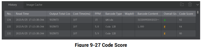
Figure 9-27 Code Score
Figure description (text version): History panel with columns No., Read Time, Output Total Count, Cost Time (ms), PPM, Barcode Type, Waybill, Barcode Content, Overall Grade and Code Score; three entries with their code scores.
- (Optional) Go to Image Settings, and adjust parameters like exposure time, gain, Gamma, light source, etc. if the code score is low.
Note: If the code score is still low after adjusting, the code may have poor printing quality.
9.5 Line Mode Settings
Line mode settings allow you to customize the specific line as input or output according to actual demands.
Go to I/O Control Settings → Line Mode Control, and set Input or Output according to actual demands.
Note:
- Only the vari-focal devices (type I, type II and type III devices) support this function.
- If the device has 4 bi-directional I/Os, Line 0 and Line 1 are inputs, and Line 2 and Line 3 are outputs by default.
- Line 0 should be the same as Line 1 (input or output), and Line 2 should be the same as Line 3 (input or output).
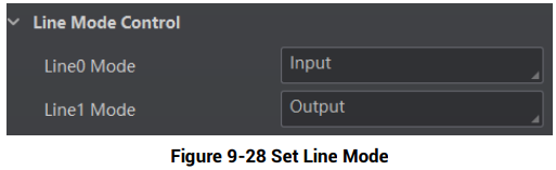
Figure 9-28 Set Line Mode
Figure description (text version): Line Mode Control group: Line0 Mode Input, Line1 Mode Output.
Słowa kluczowe
Hikrobot ID2000, add code, ROI, chessboard ROI, algorithm parameter, 1D code, 2D code, stacked code, code color, QR code, DataMatrix, quality evaluation, ISO 15416, ISO 15415, ISO 29158, code score, line mode