
9. Device Settings – Part 3 (Signal Input and Output)
…Streszczenie: Ustawienia ID2000 cz. 3: wyzwalanie wewnętrzne i zewnętrzne (programowe, sprzętowe, licznik, TCP, UDP, port szeregowy, USB, self trigger, response trigger), zatrzymanie wyzwalania, wybór i inwersja wyjścia, źródła zdarzeń LineOut oraz brzęczyk.
EN: ID2000 settings part 3: internal and external trigger (software, hardware, counter, TCP, UDP, serial, USB, self and response trigger), stop trigger, output selection and inverter, LineOut event sources and buzzer.
Dotyczy: przemysłowy czytnik kodów Hikrobot serii ID2000 (typy I–VII; Fast Ethernet, USB lub RS-232; obsługa przez klienta IDMVS i kody konfiguracyjne)
Źródło: dokumentacja producenta (Hikrobot ID2000 Series Industrial Code Reader User Manual); opisy rysunków – opracowanie Multiprojekt
Rozdział 9 „Device Settings” – części: Part 1 – Feature Tree, Reading Mode, Image Quality | Part 2 – Code Algorithm and Line Mode | Part 3 – Signal Input and Output | Part 4 – Communication and Data Processing | Part 5 – Multicast, Contrast, Statistics, Events, User Set
← poprzednia część · następna część →
9.6 Signal Input Settings
In the signal input module, you can set the trigger related parameters. You can enable trigger mode to let the acquisition of image data occur only when the trigger source is generated.
9.6.1 Set Trigger Mode
The device has 2 types of trigger mode: Internal trigger mode and external trigger mode.
- Internal Trigger Mode: The device acquires images via its internal signals.
- External Trigger Mode: The device acquires images via external signals like software signal and hardware signal. The trigger source of external trigger mode includes software, physical lines, counter, TCP, UDP, etc.
Note:
- The type VII device supports software, physical lines (LineIn 1 and Line 2), response trigger and self trigger.
- For other device types, the device with USB data interface supports only two trigger sources (USB stat and software), and the device with fast Ethernet supports all trigger sources apart from USB stat.
- For specific trigger sources, refer to the actual device you got.
- The device trigger via pressing the trigger button is supported by default. You can go to Feature Tree → Trigger and IO Control → TRIG Button Enable to disable it.
9.6.2 Enable Internal Trigger Mode
In the internal trigger mode, the device acquires images via its internal signals. You have 2 methods to enable the internal trigger mode:
- Click I/O Control Settings → Input → Trigger Mode, and select Off as Trigger Mode.
- In the live view page, click
 to enable the internal trigger mode.
9.6.3 Enable External Trigger Mode
In the external trigger mode, the device acquires images via external signals like software signal and hardware signal. You have 2 methods to enable the external trigger mode:
- Click I/O Control Settings → Input → Trigger Mode, and select On as Trigger Mode.
- In the live view page, click
 to enable the external trigger mode.
Set and Execute Software Trigger Mode
In software trigger, the software sends trigger signal to the device via I/O interface to acquire images.
Steps
- Click I/O Control Settings → Input → Trigger Mode.
- Select On as Trigger Mode.
- Select Software as Trigger Source.
- Click Execute in Trigger Source to send trigger commands.
You can also enter Auto Trigger Time, and then enable Enable Auto Trigger to let the client software automatically send trigger signal to device according to the interval you set.
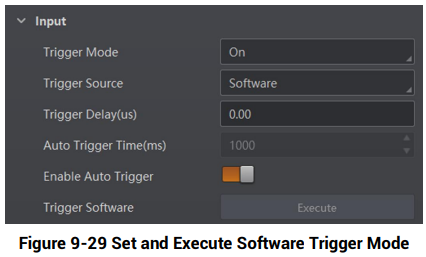
Figure 9-29 Set and Execute Software Trigger Mode
Figure description (text version): Input group: Trigger Mode On, Trigger Source Software, Trigger Delay (us) 0.00, Auto Trigger Time (ms) 1000 (greyed), Enable Auto Trigger switched on, Trigger Software Execute button.
Set and Execute Hardware Trigger Mode
Steps
- Click I/O Control Settings → Input → Trigger Mode.
- Select On as Trigger Mode.
- Select the specific line as Trigger Source according to actual demands.
Note: For the vari-focal devices (type I, type II and type III devices), you can select customized lines as Trigger Source. Refer to section Line Mode Settings for specific settings.
- Set Debounce Time and Line Out Trigger In Polarity according to actual demands.
Note:
- When selecting Rising Edge or Falling Edge as Line Out Trigger In Polarity, you can set Trigger Delay.
- When selecting Level High or Level Low as Line Out Trigger In Polarity, you can set Start Delay Time and End Delay Time according to actual demands.
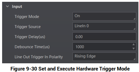
Figure 9-30 Set and Execute Hardware Trigger Mode
Figure description (text version): Input group: Trigger Mode On, Trigger Source LineIn 0, Trigger Delay (us) 0.00, Debounce Time (us) 1000, Line Out Trigger In Polarity Rising Edge.
Set and Execute Counter Trigger Mode
Counter specifies that the trigger source will be generated after the set number of valid signals appears. For example, if you set the Count Number to 3, the trigger source will be generated after 3 signals appear.
Steps
- Click I/O Control Settings → Input → Trigger Mode.
- Select On as Trigger Mode.
- Select Counter 0 as Trigger Source.
- Set Trigger Delay, Count Number, Count Source and Line Out Trigger In Polarity according to actual demands.
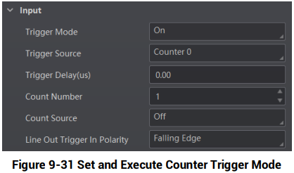
Figure 9-31 Set and Execute Counter Trigger Mode
Figure description (text version): Input group: Trigger Mode On, Trigger Source Counter 0, Trigger Delay (us) 0.00, Count Number 1, Count Source Off, Line Out Trigger In Polarity Falling Edge.
Set and Execute TCP Trigger Mode
TCP start specifies the TCP server as the source for the trigger signal. When the server receives the specified string text, the trigger signal will be outputted.
Steps
- Go to I/O Control Settings → Input → Trigger Mode.
- Select On as Trigger Mode.
- Select TCP Start as Trigger Source.
- Set following parameters according to actual demands.
- TCP Trigger Port: It sets the host port of TCP trigger.
- TCP Start Trigger Text: It sets the trigger text of TCP start, and it is Start by default.
Set and Execute UDP Trigger Mode
UDP start specifies the UDP server as the source for the trigger signal. When the server receives the specified string text, the trigger signal will be outputted.
Steps
- Go to I/O Control Settings → Input → Trigger Mode.
- Select On as Trigger Mode.
- Select UDP Start as Trigger Source.
- Set following parameters according to actual demands.
- UDP Trigger Port: It sets the host port of UDP trigger.
- UDP Start Trigger Text: It sets the trigger text of UDP start, and it is Start by default.
Set and Execute Serial Port Trigger Mode
Serial start specifies the serial port as the source for the trigger signal. When the serial port receives the specified string text, the trigger signal will be outputted.
Steps
- Go to I/O Control Settings → Input → Trigger Mode.
- Select On as Trigger Mode.
- Select Serial Start as Trigger Source.
- Set Serial Baudrate, Serial Data Bits, Serial Parity, and Serial Stop Bits.
- Set Serial Start Trigger Text that configures the trigger text of serial port start, and it is Start by default.
Set and Execute USB Trigger Mode
Steps
- Go to I/O Control Settings → Input → Trigger Mode.
- Select On as Trigger Mode.
- Select USB Start as Trigger Source.
- Set USB Baudrate, USB Data Bits, USB Parity, USB Stop Bits, and USB Start Trigger Text according to actual demands.
Set and Execute Self Trigger Mode
Self trigger allows you to trigger the device according to the trigger period you configured.
Steps
- Click I/O Control Settings → Input → Trigger Mode.
- Select On as Trigger Mode.
- Select Self Trigger as Trigger Source, set Self Trigger Period and Self Trigger Count.
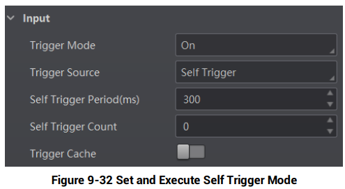
Figure 9-32 Set and Execute Self Trigger Mode
Figure description (text version): Input group: Trigger Mode On, Trigger Source Self Trigger, Self Trigger Period (ms) 300, Self Trigger Count 0, Trigger Cache off.
Note:
- If the self-trigger count is set to 0, the device can be triggered indefinitely until the execution of self-trigger stops.
- The self-trigger time shall be set to be greater than the reciprocal of the actual frame rate.
Set and Execute Response Trigger
Steps
- Click I/O Control Settings → Input → Trigger Mode.
- Select On as Trigger Mode.
- Select Response Trigger as Trigger Source, and set Trigger Sensitivity accordingly.
9.6.4 Stop Trigger
The device supports stopping trigger via TCP, UDP, I/O, serial port and USB. You can also set code reading timeout duration or max. code amount to be read to stop trigger. After stopping trigger is completed, the device cannot make response to trigger again.
Note: The type VII device supports stopping trigger via serial port, I/O, code reading timeout duration or max. code amount.
Note:
- For other device types, the device with USB data interface supports stopping trigger via USB only, and the device with fast Ethernet supports all stop trigger methods apart from the USB method.
- For specific stop trigger methods, refer to the actual device you got.
Stop Trigger via TCP
When the TCP server receives the specified string text, the trigger will be stopped.
Steps
- Go to I/O Control Settings → Stop Trigger.
- Enable TCP Stop Trigger Enable.
- Set following parameters according to actual demands.
- TCP Trigger Port: It is 2001 by default.
- TCP Stop Trigger Format: It is Str by default.
- TCP Stop Trigger Text: It sets the stop trigger text, and it is Stop by default.
Stop Trigger via UDP
When the UDP receives the specified string text, the trigger will be stopped.
Steps
- Go to I/O Control Settings → Stop Trigger.
- Enable UDP Stop Trigger Enable.
- Set following parameters according to actual demands.
- UDP Trigger Port: It is 2002 by default.
- UDP Stop Trigger Format: It is Str by default.
- UDP Stop Trigger Text: It sets the stop trigger text, and it is Stop by default.
Stop Trigger via IO
Stopping trigger via IO allows you to select hardware or software trigger source to stop the device from acquiring images.
Steps
- Go to I/O Control Settings → Stop Trigger.
- Enable IO Stop Trigger Enable.
- Select sources from LineIn 0/1/2/3 and Software Trigger End as IO Stop Trigger Selector.
- (Optional) Set trigger activation if LineIn 0/1/2/3 is selected as IO Stop Trigger Selector.
- (Optional) Click Execute in Software Stop Trigger to stop trigger if Software Trigger End is selected as IO Stop Trigger Selector.
Stop Trigger via Serial Port
When the specified serial port receives the specified string text, the trigger will be stopped.
Steps
- Go to I/O Control Settings → Stop Trigger.
- Enable Serial Stop Trigger Enable.
- Set following parameters according to actual demands.
- Serial Stop Trigger Text: It sets the trigger text of serial port stop, and it is Stop by default.
- Serial Baud Rate: It sets the baud rate of the serial port, and it is 9600 by default.
- Serial Data Bits: It sets the data bits of the serial port, and it is 8 by default.
- Serial Parity: It sets the parity of the serial port, and it is No Parity by default.
- Serial Stop Bits: It sets the stop bits of the serial port, and it is 1 by default.
Stop Trigger via USB
The USB stop trigger function means that the device receives USB commands from the external device to stop image acquisition. At this time, the device acts as a USB server to receive commands, and the external device communicating with it acts as a USB client to send commands.
Go to Feature Tree, find Stop Trigger Control, enable USB Stop Trigger Enable, set USB Stop Trigger Text, USB Baudrate, USB Data Bits, USB Parity, and USB Stop Bits according to actual demands.
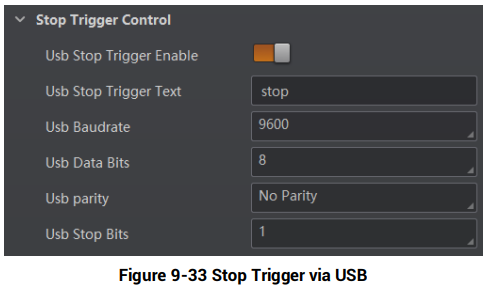
Figure 9-33 Stop Trigger via USB
Figure description (text version): Stop Trigger Control group: Usb Stop Trigger Enable on, Usb Stop Trigger Text "stop", Usb Baudrate 9600, Usb Data Bits 8, Usb Parity No Parity, Usb Stop Bits 1.
Stop Trigger via Timeout Duration
When the trigger time reaches the specified maximum value (ms), the trigger will be stopped. You can enable TimeOut Stop Trigger Enable, and set Maximum Output Limited Time according to actual demands.
Note: The range of Maximum Output Limited Time is between 0 ms and 10000 ms.

Figure 9-34 Stop Trigger via Timeout Duration
Figure description (text version): Parameters: TimeOut Stop Trigger Enable on, Maximum Output Limited Time (ms) 5000.
Stop Trigger via Code Number
This function means that the code quantity outputted by the device is restricted to the settings you configured here.
You can enable CodeNum Stop Trigger Enable, and set CodeNum Stop Trigger Min and CodeNum Stop Trigger Max according to actual demands.
Note:
- If the outputted code quantity is smaller than the configured CodeNum Stop Trigger Min, the device will output codes continuously.
- If the outputted code quantity is smaller than the configured CodeNum Stop Trigger Max, the device will stop outputting codes.
- If the outputted code quantity is between the configured CodeNum Stop Trigger Min and CodeNum Stop Trigger Max, the device will read and output codes according to trigger signals.
- If CodeNum Stop Trigger Min is the same as CodeNum Stop Trigger Max, the device will stop outputting codes when the number of outputted codes reaches the configured number.
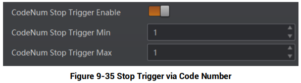
Figure 9-35 Stop Trigger via Code Number
Figure description (text version): Parameters: CodeNum Stop Trigger Enable on, CodeNum Stop Trigger Min 1, CodeNum Stop Trigger Max 1.
9.7 Signal Output Settings
9.7.1 Select Output Signal
The device’s output signal can control external devices like PLC, flashing light, etc. Click I/O Control Settings → Output → Line Out Selector to select output signal.
Note: The specific output signals may differ by device models.
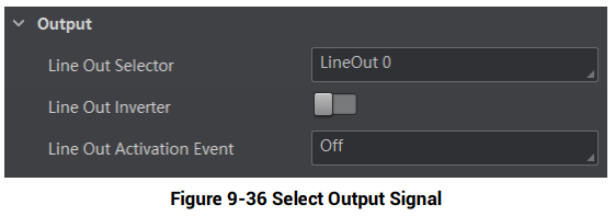
Figure 9-36 Select Output Signal
Figure description (text version): Output group: Line Out Selector LineOut 0, Line Out Inverter off, Line Out Activation Event Off.
9.7.2 Enable Line Inverter
The line inverter function allows the device to invert the electrical signal level of an I/O line, and meets requirements of different devices for high or low electrical signal level.
You can go to I/O Control Settings → Output → Line Out Inverter to enable it.
Note: The Line Out Inverter function is disabled by default.
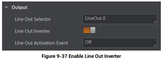
Figure 9-37 Enable Line Out Inverter
Figure description (text version): Output group: Line Out Selector LineOut 0, Line Out Inverter on, Line Out Activation Event Off.
9.7.3 Set Event Source
The device supports outputting different trigger signals according to the event source you select. Click I/O Control Settings → Output → Line Out Activation Event to select event source.
The device supports following event sources, including Off, NoCodeRead, ReadSuccess, Compare Success, and Compare Fail.
Note:
- Off refers to no event source.
- The event source parameters may differ by device model.
- No Code Read: If no code read by the device, the output signal will be triggered.
- Read Success: If the code is read by the device, the output signal will be triggered.
- Compare Success: If data comparison is successful, the output signal will be triggered.
- Compare Fail: If data comparison is failed, the output signal will be triggered.
- Command Control IO: It is controlled by the communication strings.
Note: You need to set different parameters when selecting these event sources.
Select No Code Read
If you select No Code Read as Line Out Activation Event, and you can set its output delay time and duration.
- Line Out Delay Time: It sets the delay time for outputting the output signal.
- Line Out Duration: It sets the time duration of the output signal.
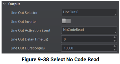
Figure 9-38 Select No Code Read
Figure description (text version): Output group: Line Out Selector LineOut 0, Line Out Inverter off, Line Out Activation Event NoCodeRead, Line Out Delay Time (us) 0, Line Out Duration (us) 10000.
Select Read Success
If you select Read Success as Line Out Activation Event, and you can set its output delay time and duration.
- Line Out Delay Time: It sets the delay time for outputting the output signal.
- Line Out Duration: It sets the time duration of the output signal.
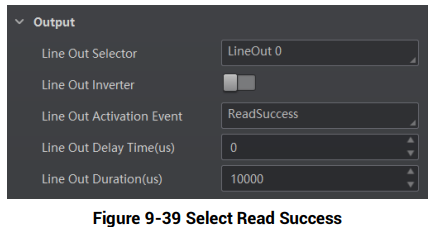
Figure 9-39 Select Read Success
Figure description (text version): Output group: Line Out Selector LineOut 0, Line Out Inverter off, Line Out Activation Event ReadSuccess, Line Out Delay Time (us) 0, Line Out Duration (us) 10000.
Select Compare Success
If you select Compare Success as Line Out Activation Event, and you can set its output delay time and duration.
- Line Out Delay Time: It sets the delay time for outputting the output signal.
- Line Out Duration: It sets the time duration of the output signal.
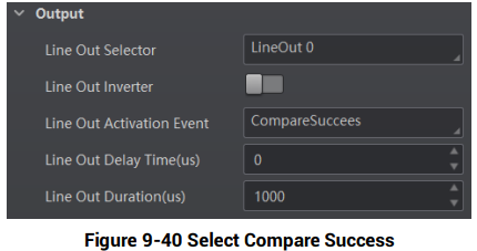
Figure 9-40 Select Compare Success
Figure description (text version): Output group: Line Out Selector LineOut 0, Line Out Inverter off, Line Out Activation Event CompareSuccess (shown as "CompareSuccees"), Line Out Delay Time (us) 0, Line Out Duration (us) 1000.
Select Compare Fail
If you select Compare Fail as Line Out Activation Event, and you can set its output delay time and duration.
- Line Out Delay Time: It sets the delay time for outputting the output signal.
- Line Out Duration: It sets the time duration of the output signal.
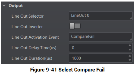
Figure 9-41 Select Compare Fail
Figure description (text version): Output group: Line Out Selector LineOut 0, Line Out Inverter off, Line Out Activation Event CompareFail, Line Out Delay Time (us) 0, Line Out Duration (us) 1000.
Select Command Control IO
If you select Command Control IO as Line Out Activation Event, and you do not need to set any parameters.
- Control Start Str: It sets the start string of command control.
- Control Stop Str: It sets the stop string of command control.
- Line Out Delay Time: It sets the delay time for outputting the output signal.
- Line Out Duration: It sets the time duration of the output signal.
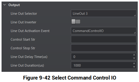
Figure 9-42 Select Command Control IO
Figure description (text version): Output group: Line Out Selector LineOut 1, Line Out Inverter off, Line Out Activation Event CommandControlIO, Control Start Str and Control Stop Str (empty), Line Out Delay Time (us) 0, Line Out Duration (us) 1000.
9.7.4 Set Buzzer
Note:
- Only type VI and type VII devices support the buzzer function.
- Make sure that the device is in the Normal mode before using the buzzer function.
The buzzer is used to indicate the device’s operation status, and you can set the buzzer function according to actual demands.
Steps
- Right click the device in Device Connection, and click Feature Tree.
- Go to Trigger and IO Control→ Buzzer Enable, and enable Buzzer Enable.
Note: After enabling Buzzer Enable, the buzzer beeps three times when the device is powered on, beeps twice when the device reads setting codes successfully, and beeps once when the device reads codes successfully.
- Set Buzzer Duration (ms) and Buzzer Frequency (hz) according to actual demands.
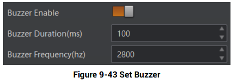
Figure 9-43 Set Buzzer
Figure description (text version): Buzzer parameters: Buzzer Enable on, Buzzer Duration (ms) 100, Buzzer Frequency (Hz) 2800.
Słowa kluczowe
Hikrobot ID2000, trigger mode, software trigger, hardware trigger, counter, TCP trigger, UDP trigger, serial trigger, USB trigger, self trigger, response trigger, stop trigger, line out, inverter, event source, No Code Read, Read Success, buzzer