
9. Device Settings – Part 5 (Multicast, Contrast, Statistics, Events, User Set)
…Streszczenie: Ustawienia ID2000 cz. 5: multicast, sieć główny–podrzędny (main-sub), kontrola porównania kodów, statystyki odczytu, raport zdarzeń diagnostycznych i zestawy ustawień użytkownika.
EN: ID2000 settings part 5: multicast, main-sub networking, contrast control, reading statistics, diagnostic event report and user sets.
Dotyczy: przemysłowy czytnik kodów Hikrobot serii ID2000 (typy I–VII; Fast Ethernet, USB lub RS-232; obsługa przez klienta IDMVS i kody konfiguracyjne)
Źródło: dokumentacja producenta (Hikrobot ID2000 Series Industrial Code Reader User Manual); tabele i uwagi przepisane z obrazów na tekst; opisy rysunków – opracowanie Multiprojekt
Rozdział 9 „Device Settings” – części: Part 1 – Feature Tree, Reading Mode, Image Quality | Part 2 – Code Algorithm and Line Mode | Part 3 – Signal Input and Output | Part 4 – Communication and Data Processing | Part 5 – Multicast, Contrast, Statistics, Events, User Set
← poprzednia część
9.10 Set Multicast
The multicast function is used to let multiple devices have the same trigger number when they are acquiring images and analyzing codes at the same time. When each device sends the trigger number and outputted images to the code reading platform, the platform will integrate the images with the same trigger number as the information of the same package. The main principle of the multicast function is to set one main device among multiple devices, and remaining devices are called sub devices. As the first triggered device, the main device sends trigger numbers to sub devices each time, and sub devices replace their trigger numbers with received ones so that all devices have the same trigger numbers.
Follow the steps below to set multicast function according to actual demands.
Steps
- Right click the device in Device Connection, and click Feature Tree.
- Go to Multi Camera Control, set one device as Main in Multi Camera Mode according to actual demands.
Note: You can set 32 sub devices at most.
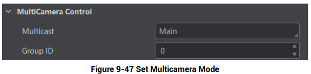
Figure 9-47 Set Multicamera Mode
Figure description (text version): MultiCamera Control group: Multicast Main, Group ID 0.
- Set GroupID.
Note: You should set the same GroupID for devices in the same multicast system.
9.11 Main-Sub Networking
When multiple devices acquire images and parse codes at the same time, the main-sub networking function enables multiple devices to work together.
The main principle of main-sub networking is to set one of the multiple devices as the main device (main station), and the other devices as sub devices (sub station). The sub devices send the code results to the main device that integrates or forwards, and sends the code results to the connected PC or client software to realize the collaborative work function of multiple devices.
Before You Start
Make sure that the device mode is Normal and Tigger Mode is On before using this function.
Note: The function of main-sub networking may differ by device models.
Steps
- Go to Multi Camera Control, and select Multi Station Work Mode according to actual demands.
- Off: This function is disabled.
- Independent: The main device and the sub devices are triggered respectively, and the sub devices send the code reading result to the main device. The main device directly formats and outputs the sub devices’ data according to the formatting rules without data processing. It is mainly used for the scenario of multiple assembly lines.
- Cooperation: The main device and the sub devices use the same trigger, the sub devices send the code reading result to the main device for data processing, and then format and output the data after the fusion of the main and sub devices according to the formatting rules. It is mainly used to the scenario where the field of view is insufficient, and multiple codes are read together to integrate the output. In most cases, this mode is used.
- Set role for different devices in Station Role. Main is the main device, and Sub is the sub device
Note: There is only one main device in the same main-sub networking (same group ID).
- Set Station Port to configure the main station’s port number and communicate with the sub station.
- (Optional) Enable Client Display Sub Enable to let the main device display the code reading images from the sub station.
Note: The client software of the main device can acquire images after enabling Client Display Sub Enable.
- Set MS Group ID ranging from 100 to 200 to configure the main-sub networking group ID.
Note: Two-way visiting is not allowed among different network groups.
- (Optional) View enumerated sub station quantity via Sub Station Total as a main station role.
- (Optional) View sub station information after entering Query Sub Station ID as a main station role.
- Sub Station IP: The IP information of the sub station.
- Sub Station Connect: The connection status of the sub station. 1 stands for normal data transmission. Otherwise, it is disconnected.
- Sub Station UN: The user name information of the sub station.
- Sub Station MN: The product model information of the sub station.
- Sub Station SN: The serial number of the sub station.
- (Optional) View main station information when the Station Role is Sub.
- Main Station IP: The IP information of the main station.
- Main Station Connect: The connection status of the main station. 1 stands for normal data transmission. Otherwise, it is disconnected.
- Main Station UN: The user name information of the main station.
- Main Station MN: The product model information of the main station.
- Main Station SN: The serial number of the main station.
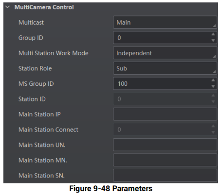
Figure 9-48 Parameters
Figure description (text version): MultiCamera Control group: Multicast Main, Group ID 0, Multi Station Work Mode Independent, Station Role Sub, MS Group ID 100, Station ID 0, Main Station IP (empty), Main Station Connect 0, Main Station UN, Main Station MN and Main Station SN (empty).
9.12 Contrast Control Settings
Note: You need to set the device’s operation mode to Normal before using this function.
The contrast control function compares the data that the device reads with preset data and outputs contrast result. The result can be used as the event source of trigger signal, including Contrast Success and Contrast Fail. This function has two ways to contrast, including regular contrast and consecutive number contrast.
Regular Contrast
The regular contrast requires you to set code contents in advance, and the client software will contrast the data that the device reads with preset contents and outputs comparison result.
Steps
- Right click the device in Device Connection, and click Feature Tree.
- Go to Contrast Control, enable Contrast Enable, and select Regular as Contrast Rules.
- Set Start Position that means the stating position of the comparison.
- Set Character Number that means the comparison quantity.
- Set code contents in Wildcard String.
Note: You can use wildcards * and ?. * stands for multiple characters and ? stands for one character. * can be used only once and ? can be used many times.
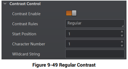
Figure 9-49 Regular Contrast
Figure description (text version): Contrast Control group: Contrast Enable on, Contrast Rules Regular, Start Position 1, Character Number 1, Wildcard String (empty).
Consecutive Number Contrast
The consecutive number contrast requires you to set consecutive code rules, and the client software will contrast the data that the device reads with preset rules and outputs contrast result.
Steps
- Right click the device in Device Connection, and click Feature Tree.
- Go to Contrast Control, enable Contrast Enable, and select Consecutive Number as Compare Rules.
- Set Start Position that means the stating position of the comparison.
- Set Digital Number that means the comparison quantity.
- Set Step that means the client software will increase or decrease the preset value after each comparison according the step you set.
Note:
- If the preset value after increase or decrease exceeds the digital number you set, the preset value will become 0.
- The base value displays the preset value.
- (Optional) Click Execute in Contrast Reset to reset comparison. After that, the client software will use the first code it reads as the preset value.
Here we take start position (3), digital number (2) and step (2) as an example to explain the consecutive number comparison:- If the first code that the device reads is ur96k, and then the preset value is 96. The preset value increases to 98 (96+2).
- If the second code is yr98kjkfd, and comparison succeeds. The preset value increases to 100 (98+2).
- If the third code is kl99fjkd, and comparison fails. The preset value does not increase.
- If the fourth code is kl00djf, and comparison succeeds. The preset value increases to 02 (00+2).
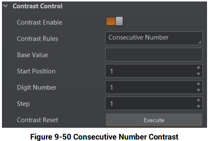
Figure 9-50 Consecutive Number Contrast
Figure description (text version): Contrast Control group: Contrast Enable on, Contrast Rules Consecutive Number, Base Value (empty), Start Position 1, Digit Number 1, Step 1, Contrast Reset (Execute).
9.13 Statistics Information
The statistics information in the feature tree helps you to count data related with code reading.
Note: You need to set the device’s operation mode to Normal before using this function.
Steps
- Right click the device in Device Connection, and click Feature Tree.
- Go to feature tree, find Statistics Info., and select Statistics Mode:
- All Frames means the client software will display all data since the device is powered on.
- Latest Frames means the client software will display data of the last 10 frames.
- View related parameters.
- (Optional) Click Execute in Reset Statistics to reset statistics information.
Table 9-20 Parameter Description
| Parameter Name | Description |
|---|---|
| Total Frame Number | The total frame quantity. |
| Read Frame Number | The quantity of frames in which codes have been read. |
| Noread Frame Number | The quantity of frames in which codes have not been read. |
| Read Rate | It refers to the code reading ratio. |
| Algo Time Ave. | The average time of the algorithm, in ms. |
| Algo Time Max. | The max. time of the algorithm, in ms. |
| Algo Time Min. | The min. time of the algorithm, in ms. |
| Read Time Ave. | The average time of code reading, in ms. |
| Read Time Max. | The max. time of code reading, in ms. |
| Read Time Min. | The min. time of code reading, in ms. |
| Reset Statistics | Click Execute to reset the statistics information. |
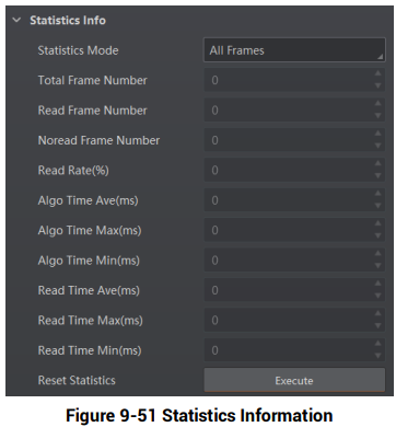
Figure 9-51 Statistics Information
Figure description (text version): Statistics Info group: Statistics Mode All Frames, followed by read-only counters (Total Frame Number, Read Frame Number, Noread Frame Number, Read Rate (%), Algo Time Ave/Max/Min (ms), Read Time Ave/Max/Min (ms), all 0) and Reset Statistics (Execute).
9.14 Diagnose Event Report
The diagnose event report function monitors memory and CPU usage rate, and let you know when there is a crash, higher CPU usage rate, insufficient memory, and other events.
Steps
- Right click the device in Device Connection, and click Feature Tree.
- Go to feature tree, find Diagnose Event Report.
- View relation information.
- (Optional) Click Execute in Reset Event to clear all information.
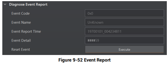
Figure 9-52 Event Report
Figure description (text version): Diagnose Event Report group with read-only fields Event Code, Event Name, Event Report Time and Event Detail, and Reset Event (Execute).
9.15 User Set Customization
In Configuration Management, you can set and manage the user set. A user set is a group of parameter values with all the settings needed to control the device, and you can save, load and switch different user sets.
- Save Settings: If you have set the device parameters as desired, you can save them into the user set. Go to Config Management → Save Settings, and click UserSet1, UserSet2, or UserSet3 to save the current device settings.
- Load Settings: You can load the user set to restore the device to the saved group of parameter values again if required. Go to Config Management → Load Settings, and click Default, UserSet1, UserSet2, or UserSet3 to load settings.
Note: Default refers to restoring the device parameter settings to the factory ones.
- Start Settings: The selected user set will be automatically loaded after the device being powered on. For example, if you select Default, the device parameter settings will be restored to the factory settings.
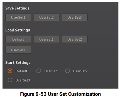
Figure 9-53 User Set Customization
Figure description (text version): Configuration panel: Save Settings buttons UserSet1–UserSet3; Load Settings buttons Default and UserSet1–UserSet3; Start Settings radio buttons Default (selected), UserSet1, UserSet2, UserSet3.
Słowa kluczowe
Hikrobot ID2000, multicast, main-sub networking, Group ID, contrast control, wildcard, consecutive number, statistics, read rate, diagnose event report, user set, UserSet1