
1. Appearance
Streszczenie: Wygląd czytnika kodów ID3000 (typ I z pokrętłem ostrości i typ II) oraz opis elementów: złącze 17-pin, wskaźniki OK/NG, PWR, STS, LNK, osłona obiektywu, źródło światła LED i przycisk wyzwalania.
EN: ID3000 code reader appearance (Type I and Type II) and component description: 17-pin interface, OK/NG, PWR, STS and LNK indicators, lens cap, LED light source and trigger button.
Dotyczy: przemysłowy czytnik kodów Hikrobot serii ID3000 (złącze M12 17-pin, Fast Ethernet, RS-232; obsługa przez klienta IDMVS)
Źródło: dokumentacja producenta (Hikrobot ID3000 Series Industrial Code Reader User Manual, V3.1.0); tabele i uwagi przepisane z obrazów na tekst, opisy rysunków – opracowanie Multiprojekt
Note: Appearance here is for reference only. Refer to the device’s specification for detailed dimension information.
Device Views
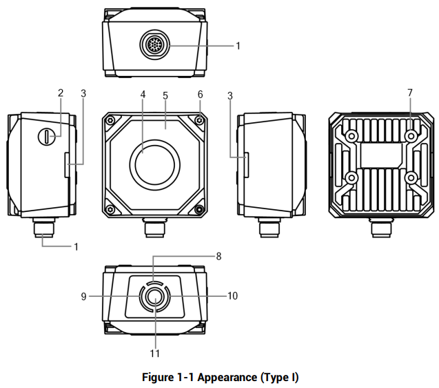
Figure 1-1 Appearance (Type I)
Figure description (text version): Technical drawing in five views (top, left, front, right, rear) plus bottom view. Callouts: 1 – 17-pin interface, 2 – focus knob, 3 – OK/NG indicator, 4 – lens cap, 5 – light source, 6 – screw, 7 – screw hole, 8 – PWR indicator, 9 – STS indicator, 10 – LNK indicator, 11 – button. See Table 1-1.
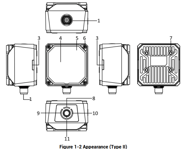
Figure 1-2 Appearance (Type II)
Figure description (text version): Technical drawing of the Type II device (square lens cap, no focus knob) in the same views as Type I. Callouts 1 and 3–11 as in Table 1-1.
Component Description
Table 1-1 Appearance Description
| No. | Name | Description |
|---|---|---|
| 1 | 17-Pin Interface | It provides power, input/output, Ethernet, and serial port signal. The interface is designed with screw threads to tighten connection between the device and cable, and thus avoiding influence caused by vibration. |
| 2 | Focus Knob | It is used to adjust focal length manually. Note: the focus knob may differ by device models, and some models do not have a focus knob. |
| 3 | OK/NG Indicator | It indicates code reading result. • The indicator is orange when the device is starting up. • The indicator is red after the device is powered on. • The indicator is flashing green after the device reads barcodes, and it is solid green if the device reads barcodes continuously. |
| 4 | Lens Cap | It can be replaced with other lens cap. Refer to the device’s specification for details. |
| 5 | Light Source | It refers to LED lamps providing light for improving code reading effect. Note: • The default color of LED lamps is white. Red, blue and IR are optional. • The quantity of LED lamps may differ by device models. |
| 6 | Screw | It refers to the screw between device body and lens cap. |
| 7 | Screw Hole | It is used to fix the device to installation position. You should use M4 screw. |
| 8 | PWR Indicator | It is the power indicator. The indicator is green when the device operates normally. Otherwise, it is red. |
| 9 | STS Indicator | It is the device status indicator. The indicator is green when the device operates normally. When the device starts up or exception occurs, it is red. |
| 10 | LNK Indicator | It is network status indicator. The indicator is flashing green when the network transmission is normal. Otherwise, it is unlit. |
| 11 | Button | • When the device is in continuous acquisition mode, press the button and the device enters trigger mode. • When the device is in trigger mode, press the button and the device triggers once. |
Słowa kluczowe
Hikrobot ID3000, appearance, wygląd, Type I, Type II, focus knob, OK/NG indicator, PWR, STS, LNK, lens cap, light source, LED, button, trigger
No comments to display
No comments to display