
6. Client Software Layout
Streszczenie: Układ okna klienta IDMVS dla ID3000: pasek menu, pasek narzędzi, obszar konfiguracji urządzenia, okno podglądu na żywo i panel historii oraz moduły konfiguracji (obraz, algorytm, I/O, przetwarzanie danych, komunikacja, zarządzanie konfiguracją).
EN: IDMVS client layout for the ID3000: menu bar, control toolbar, device configuration area, live view and history panel, plus the configuration modules.
Dotyczy: przemysłowy czytnik kodów Hikrobot serii ID3000 (złącze M12 17-pin, Fast Ethernet, RS-232; obsługa przez klienta IDMVS)
Źródło: dokumentacja producenta (Hikrobot ID3000 Series Industrial Code Reader User Manual, V3.1.0); tabele i uwagi przepisane z obrazów na tekst, opisy rysunków – opracowanie Multiprojekt
Main Window
After connecting to the device, the client software can read the device information and display it.
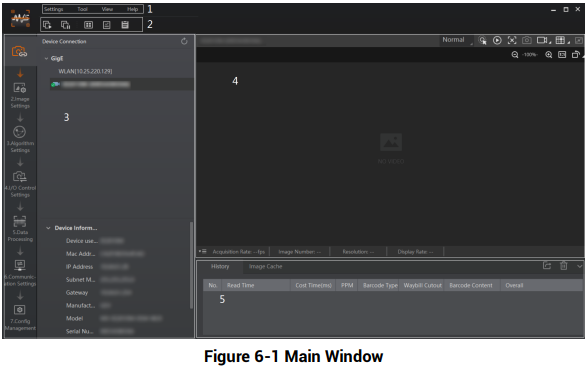
Figure 6-1 Main Window
Figure description (text version): IDMVS main window. Callouts: 1 – menu bar (Settings, Tool, View, Help); 2 – control toolbar; 3 – device configuration area (Device Connection with the GigE device list, configuration steps on the left and Device Information below); 4 – live view window with operating mode selector and acquisition buttons; 5 – history record panel (History / Image Cache) with columns No., Read Time, Cost Time, PPM, Barcode Type, Barcode Content, Overall. See Table 6-1.
Note: The specific interfaces of the client software may differ by its versions.
Table 6-1 Main Window Description
| No. | Name | Description |
|---|---|---|
| 1 | Menu Bar | The menu bar displays function modules, including Settings, Tool, View, and Help. |
| 2 | Control Toolbar | The control toolbar provides quick operations for the device. You can click different icons to start or stop batch acquisition, change window layout, view statistics information, and device log. |
| 3 | Device Configuration Area | You can connect or disconnect device, set parameters, and modify device IP address in this area. |
| 4 | Live View Window | This area displays the acquisition images and algorithm reading result in real-time. You can click different icons to capture and save image, record, etc. |
| 5 | History Record and Image Cache | This area displays different barcode information read by the device in real-time, including read time, cost time, code type, content, code score, etc. You can also set image cache here. |
Device Configuration Area
You can set device parameters in device configuration area.
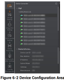
Figure 6-2 Device Configuration Area
Figure description (text version): Left part of the IDMVS window: vertical step bar (Image Settings, Algorithm Settings, I/O Control Settings, Data Processing, Communication Settings, Config Management), the Device Connection list with GigE devices and the Device Information panel (Device user ID, MAC address, IP address, Subnet mask, Gateway, Manufacturer).
Table 6-2 Device Configuration Description
| No. | Module Name | Description |
|---|---|---|
| 1 | Device Connection | You can connect or disconnect device, modify device IP address, view device information, etc. |
| 2 | Image Settings | You can set image parameters, light parameters, etc. |
| 3 | Algorithm Settings | You can add different barcodes, set barcode number, etc. |
| 4 | I/O Control Settings | You can set parameters related with input and output. |
| 5 | Data Processing | You can set filter rule for output result. |
| 6 | Communication Settings | You can select different communication protocols, and set related parameters for output result. |
| 7 | Configuration Management | You can save and load user parameters, and restart the device. |
Słowa kluczowe
Hikrobot ID3000, IDMVS, main window, menu bar, control toolbar, device configuration area, live view, history record, image cache, image settings, algorithm settings, I/O control, data processing, communication settings, configuration management
No comments to display
No comments to display