
4. Installation
Streszczenie: Instalacja czytnika ID3000: akcesoria (kabel 17-pin, zasilacz, kabel sieciowy, śruby M4, wspornik), dwie metody montażu na wspornik i podłączenie zasilania oraz sieci.
EN: ID3000 installation: accessories (17-pin cable, power supply, network cable, M4 screws, bracket), two bracket mounting methods and power/network connection.
Dotyczy: przemysłowy czytnik kodów Hikrobot serii ID3000 (złącze M12 17-pin, Fast Ethernet, RS-232; obsługa przez klienta IDMVS)
Źródło: dokumentacja producenta (Hikrobot ID3000 Series Industrial Code Reader User Manual, V3.1.0); tabele i uwagi przepisane z obrazów na tekst, opisy rysunków – opracowanie Multiprojekt
4.1 Installation Preparation
You need to prepare following accessories before installation.
Table 4-1 Accessories
| No. | Name | Quantity | Description |
|---|---|---|---|
| 1 | 17-Pin Cable | 1 | It refers to the supplied 17-pin cable that is included in the package. |
| 2 | Power Adapter or Switch Power Supply | 1 | You should select suitable power adapter or switch power supply according to the device power supply and consumption. You need to purchase separately. |
| 3 | Network Cable | 1 | It refers to a RJ45 to RJ45 fast Ethernet cable. You need to purchase separately. |
| 4 | M4 Screw | 4 | It refers to the supplied M4 screw that is used to fix the device to installation position. |
| 5 | Bracket | 1 | It is used to fix the device, and you need to purchase separately. |
4.2 Install Device
Before You Start
- Make sure the device in the package is in good condition and all the assembly parts are included.
- Make sure that all the related devices are powered off during the installation.
Steps
- Use M4 screw to fix the device to the bracket, and then install it to the installation position.
Note: Two installation methods are available, and you can select it according to actual demands.
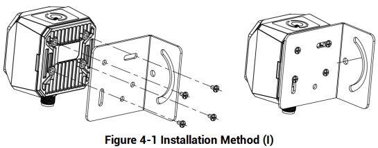
Figure 4-1 Installation Method (I)
Figure description (text version): Mounting drawing: an angle bracket is fixed with four M4 screws to the rear (heat-sink side) of the device; the bracket has slotted holes for fixing to the installation position.
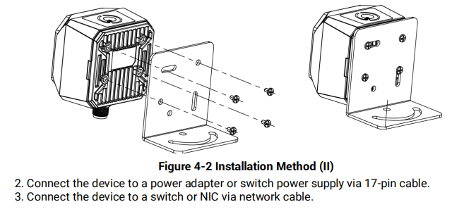
Figure 4-2 Installation Method (II)
Figure description (text version): Mounting drawing: the angle bracket is fixed with four M4 screws in a second orientation, so the device faces a different direction relative to the mounting surface. The image also shows installation steps 2 and 3 listed below.
- Connect the device to a power adapter or switch power supply via 17-pin cable.
- Connect the device to a switch or NIC via network cable.
Słowa kluczowe
Hikrobot ID3000, installation, instalacja, montaż, accessories, 17-pin cable, power adapter, network cable, M4 screw, bracket, wspornik
No comments to display
No comments to display