
6. Parameter Description – Part 3 (Group P4)
Streszczenie: Opis parametrów KE600 (część 3 z 8): zaciski wejściowe: funkcje DI 0–50 (D1–D10), sterowanie 2- i 3-przewodowe, krzywe AI, wejście impulsowe HDI, opóźnienia i logika DI.
EN: KE600 parameter description (part 3 of 8): input terminals: DI functions 0–50 (D1–D10), two-/three-wire control, AI curves, HDI pulse input, DI delays and logic.
Dotyczy: falownik wektorowy z zamkniętą pętlą Micno KE600 (zasilanie 3AC 220 V, 3AC 380 V, 3AC 660 V; moce 1,5–630 kW)
Źródło: dokumentacja producenta (Micno KE600 Series Inverter User Manual); tabele przepisane z obrazów na tekst, opisy rysunków – opracowanie Multiprojekt
Nawigacja: część 3 z 8 · poprzednia: ← Part 2 (Groups P1–P3) · następna: Part 4 (Groups P5–P6) →
Group P4 Input Terminal
The standard Inverter has 7 multifunctional digital input terminals (HDI can be used as high speed pulse input terminal) and two analog input terminals.
Digital input terminal functions
| Parameter | Name | Factory default |
|---|---|---|
| P4-00 | D1 terminal function | 1 |
| P4-01 | D2 terminal function | 2 |
| P4-02 | D3 terminal function | 0 |
| P4-03 | D4 terminal function | 0 |
| P4-04 | D5 terminal function | 0 |
| P4-05 | D6 terminal function | 0 |
| P4-06 | D7/HDI terminal function | 0 |
| P4-07 | D8 terminal function | 0 |
| P4-08 | D9 terminal function | 0 |
| P4-09 | D10 terminal function | 0 |
These parameters are used to set the functions of the multifunctional digital input terminals.
Note: D8, D9 and D10 are from the I/O extension card
Digital input (DI) terminal functions – setting values for P4-00 … P4-09
| Setting value | Function | Description |
|---|---|---|
| 0 | No function | The no operation function can be set on the unused terminals so as to prevent error action. |
| 1 | Forward (FWD) | Control the inverter forward and reverse via the external terminals. |
| 2 | Reverse (REV) | Control the inverter forward and reverse via the external terminals. |
| 3 | Three-line running control | This terminal is used to confirm that the inverter running mode is three-line control mode. Refer to P4-11 (terminal command mode) for details. |
| 4 | Forward Jog (FJOG) | FJOG refers to Jog forward running, RJOG refers to Jog reverse running. Regarding Jog running frequency and Jog ACC/DEC time, please refer to F8-00, F8-01 and F8-02. |
| 5 | Reverse Jog (RJOG) | See Forward Jog (FJOG). |
| 6 | Terminal UP | When the frequency is given by the external terminals, it is used as increment and decrement commands of frequency modification. When the frequency source is set by digital, it can be used to adjust the setting frequency. |
| 7 | Terminal DOWN | See Terminal UP. |
| 8 | Coast to stop | The inverter locks the output, and the motor stop process is beyond the inverter control. This mode is the same as the meaning of coast-to-stop as described in P6-10. |
| 9 | Fault reset (RESET) | External fault reset function. It is the same as the function of RESET key on the keyboard. Using this function can realize long-distance fault reset. |
| 10 | Pause running | The inverter decelerates to stop, but all the running parameters are in the memory status, such as PLC parameter, wobble frequency parameter and PID parameter. After this signal disappears, the inverter restores to the status before stopping. |
| 11 | External fault normally open input | After the signal is sent to the inverter, the inverter reports fault E-15 and acts according to the fault protection action mode (see P9-47). |
| 12 | Multi-step speed terminal 1 | It can realize 16 steps or 16 other command settings through 16 statuses of the four terminals. See attached table 1. |
| 13 | Multi-step speed terminal 2 | It can realize 16 steps or 16 other command settings through 16 statuses of the four terminals. See attached table 1. |
| 14 | Multi-step speed terminal 3 | It can realize 16 steps or 16 other command settings through 16 statuses of the four terminals. See attached table 1. |
| 15 | Multi-step speed terminal 4 | It can realize 16 steps or 16 other command settings through 16 statuses of the four terminals. See attached table 1. |
| 16 | ACC/DEC time selection terminal 1 | It can select four types of ACC/DEC time through 4 statuses of the two terminals. See attached table 2. |
| 17 | ACC/DEC time selection terminal 2 | It can select four types of ACC/DEC time through 4 statuses of the two terminals. See attached table 2. |
| 18 | Main frequency source switching | Used to switch different frequency source. According to the setting of frequency source selection (P0-07), when setting switching between two frequency sources is frequency source, it can achieve switching two frequency sources via this terminal. |
| 19 | UP and DOWN setting clear (terminal and keyboard) | When the frequency reference is digital frequency reference, this terminal can be used to clear the frequency value modified by UP/DOWN and thus restore the reference frequency to the setting value of P0-08. |
| 20 | Running command switching terminal | When the command source (P0-02) is set to 1, it performs switching between terminal control and keyboard control via this terminal. When the command source (P0-02) is set to 2, it performs switching between communication control and keyboard control via this terminal. |
| 21 | ACC/DEC invalid | Protect the inverter from being affected by the external signals (except stop command), and maintain the current frequency. |
| 22 | PID pause | PID is invalid temporarily, and the inverter maintains the current frequency output, no longer adjusts PID of frequency source. |
| 23 | PLC status reset | PLC pauses during the execution process. When it runs again, it can restore to the initial status of simple PLC via this terminal. |
| 24 | Wobble frequency pause | The inverter outputs the central frequency. Wobble frequency function pauses. |
| 25 | Counter input | The input terminal of counting pulse. |
| 26 | Counter reset | Clear the counter status. |
| 27 | Length count input | Input terminal of length counting. |
| 28 | Length reset | Length clear. |
| 29 | Torque control invalid | Torque control is invalid, the inverter adopts speed control mode. |
| 30 | PULSE frequency input (only valid for HDI) | HDI is pulse input terminal. |
| 31 | Reserved | Reserved. |
| 32 | DC braking command | When this terminal is valid, the inverter directly switches to DC braking status. |
| 33 | External fault normally close input | After the external fault normally close signal is sent to the inverter, the inverter reports fault E-15 and stops. |
| 34 | Frequency modification enabled | If this function is valid, the inverter does not respond to the frequency changing, until this terminal is invalid. |
| 35 | PID action direction reverse | When this terminal is valid, PID action direction is the opposite of value set by PA-03. |
| 36 | External stop terminal 1 | The inverter can be stopped by this terminal under keypad control, which has the same function as STOP key. |
| 37 | Control command switching terminal 2 | Used to switch between terminal control and communication control. If command source selection is set to terminal control, then the system switches to communication control when the terminal is valid, vice versa. |
| 38 | PID integration stop | When this terminal is valid, PID integration adjustment function will stop working, but PID ratio adjustment and differential adjustment functions are still valid. |
| 39 | Switch frequency source A to preset frequency | When this terminal is valid, frequency source A is replaced by preset frequency (P0-08). |
| 40 | Switch frequency source B to preset frequency | When this terminal is valid, frequency source B is replaced by preset frequency (P0-08). |
| 41 | Reserved | Reserved. |
| 42 | Reserved | Reserved. |
| 43 | PID parameter switching | When PID parameter switching condition is DI terminal (PA-18=1) and this terminal is invalid, PID parameter is determined by PA-05 ~ PA-07. When this terminal is valid, PID parameter is determined by PA-15 ~ PA-17. |
| 44 | Customized fault 1 | When customized fault 1 and 2 are valid, the inverter alarms E-27 and E-28, which would be processed according to the action mode set by P9-49. |
| 45 | Customized fault 2 | See Customized fault 1. |
| 46 | Speed control/torque control switching | Make the inverter switch between speed control and torque control mode. When this terminal is invalid, the inverter runs at the mode set by A0-00 (speed/torque control mode), the inverter switches to another mode when the terminal is valid. |
| 47 | Emergency stop | When the terminal is valid, the inverter stops with fastest speed; during the process, the current is as upper limits are set. This function is applied in the situation in which the inverter needs to stop ASAP when the system is in emergency status. |
| 48 | External stop terminal 2 | In any control mode (keypad control, terminal control, communication control), the inverter can decelerate to stop via this terminal and the deceleration time is DEC time 4. |
| 49 | Deceleration DC braking | When this terminal is valid, the inverter decelerates to the stop DC braking starting frequency, then switches to DC braking status. |
| 50 | The running time reset | When the terminal is valid, the inverter will clear the running time to zero; this function needs to be used together with timing running (P8-42) and running time arrival (P8-53). |
Attached table 1 – multi-step command selection (K4…K1)
| K4 | K3 | K2 | K1 | Command setting | Corresponding parameter |
|---|---|---|---|---|---|
| OFF | OFF | OFF | OFF | Multi-step command 0 | PC-00 |
| OFF | OFF | OFF | ON | Multi-step command 1 | PC-01 |
| OFF | OFF | ON | OFF | Multi-step command 2 | PC-02 |
| OFF | OFF | ON | ON | Multi-step command 3 | PC-03 |
| OFF | ON | OFF | OFF | Multi-step command 4 | PC-04 |
| OFF | ON | OFF | ON | Multi-step command 5 | PC-05 |
| OFF | ON | ON | OFF | Multi-step command 6 | PC-06 |
| OFF | ON | ON | ON | Multi-step command 7 | PC-07 |
| ON | OFF | OFF | OFF | Multi-step command 8 | PC-08 |
| ON | OFF | OFF | ON | Multi-step command 9 | PC-09 |
| ON | OFF | ON | OFF | Multi-step command 10 | PC-10 |
| ON | OFF | ON | ON | Multi-step command 11 | PC-11 |
| ON | ON | OFF | OFF | Multi-step command 12 | PC-12 |
| ON | ON | OFF | ON | Multi-step command 13 | PC-13 |
| ON | ON | ON | OFF | Multi-step command 14 | PC-14 |
| ON | ON | ON | ON | Multi-step command 15 | PC-15 |
When the frequency source selection is multi-step speed, 100% of PC-00~PC-15 correspond to P0-10 (maximum frequency).
Multi-step command not only can set as multi-step speed, but also can set as PID given source, to meet the requirement of need to switch between different given values.
Attached table 2 – ACC/DEC time selection
| Terminal 2 | Terminal 1 | Acceleration or deceleration time selection | Corresponding parameters |
|---|---|---|---|
| OFF | OFF | ACC time/DEC time 1 | P0-17, P0-18 |
| OFF | ON | ACC time/DEC time 2 | P8-03, P8-04 |
| ON | OFF | ACC time/DEC time 3 | P8-05, P8-06 |
| ON | ON | ACC time/DEC time 4 | P8-07, P8-08 |
| Parameter | Name | Factory default | Setting range |
|---|---|---|---|
| P4-10 | Terminal filter time | 0.010s | 0.000s ~ 1.000s |
It is used to set the sensitivity of DI terminal. If the digital input terminal is vulnerable to interferences and may cause error action, it can increase this parameter value to enhance the anti-interference capability.
However, this operation will reduce the sensitivity of DI terminal.
| Parameter | Name | Factory default | Setting range |
|---|---|---|---|
| P4-11 | Terminal command mode | 0 | 0: Two-line mode 1 1: Two-line mode 2 2: Three-line mode 1 3: Three-line mode 2 |
This parameter defines four different modes of controlling the operation of the inverter via the external terminals.
0: Two-line running mode 1: This is the most common mode. The forward/reverse rotation of the motor is decided by the commands of FWD and REV terminals.
Two-line mode 1 – terminal settings
| Terminal | Setting value | Description |
|---|---|---|
| DIx | 1 | Forward running (FWD) |
| DIy | 2 | Reverse running (REV) |
Figure 6-5 Two-line running mode 1 – logic
| K1 | K2 | Running command |
|---|---|---|
| 0 | 0 | Stop |
| 0 | 1 | Reverse |
| 1 | 0 | Forward |
| 1 | 1 | Stop |
Diagram description (text version): Switch K1 connects DIx (Forward, FWD) and switch K2 connects DIy (Reverse, REV) to COM (digital common terminal).
1: Two-line running mode 2: When this mode is adopted, REV is enabled terminal. The direction is determined by the status of FWD.
Two-line mode 2 – terminal settings
| Terminal | Setting value | Description |
|---|---|---|
| DIx | 1 | Forward running (FWD) |
| DIy | 2 | Forward running (REV) – as in the source; in this mode DIy determines the running direction |
Two-line running mode 2 – logic (figure captioned “Figure 6-6 Three-line Running Mode 2” in the source)
| K1 | K2 | Running command |
|---|---|---|
| 0 | 0 | Stop |
| 0 | 1 | Stop |
| 1 | 0 | Forward |
| 1 | 1 | Reverse |
Diagram description (text version): Switch K1 connects DIx (Forward, FWD) and switch K2 connects DIy (Reverse, REV) to COM (digital common terminal); K1 enables running and K2 selects the direction.
2: Three-line running mode 1: In this mode, DIn is enabled terminal, and the direction is controlled by FWD and REV respectively. However, the pulse is enabled through disconnecting the signal of DIn terminal when the inverter stops.
Three-line mode 1 – terminal settings
| Terminal | Setting value | Description |
|---|---|---|
| DIx | 1 | Forward running (FWD) |
| DIy | 2 | Reverse running (REV) |
| DIn | 3 | Three-line running control |
To make the inverter run, users must close DIn terminal firstly. It can achieve the motor forward or reverse control via pulse rising of DIx or DIy.
It can achieve the inverter stop via cutting off DIn terminal signal. DIx. DIy. DIn are DI1~DI6, HDI multifunctional input terminals, the valid input of DIx (DIy) is pulses signal, and the valid input of DIn is level signal.
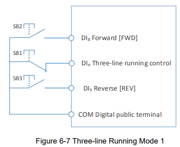
Diagram description (text version): Figure 6-7 Three-line running mode 1: push button SB2 (normally open) connects DIx (Forward, FWD), push button SB1 (normally closed) connects DIn (three-line running control – stop) and push button SB3 (normally open) connects DIy (Reverse, REV) to COM (digital common terminal).
Where,
SB2: Forward rotation button
SB3: Reverse rotation button
3: Three-line running mode 2: In this mode, DIn is enabled terminal, and the running command is given by FWD, while the direction is determined by the status of REV. Stop command is performed through disconnecting the DIn signal.
Three-line mode 2 – terminal settings
| Terminal | Setting value | Description |
|---|---|---|
| DIx | 1 | Forward running (FWD) |
| DIy | 2 | Reverse running (REV) |
| DIn | 3 | Three-line running control |
To make the inverter run, users must close DIn terminal firstly, and then the motor running signal will be generated by DIx pulse rising edge and the motor direction signal will be generated by Dy status.
It can achieve the inverter stop via cutting off DIn terminal signal. DIx. DIy. DIn are DI1~DI6, HDI multifunctional input terminals, the valid input of DIx is pulses signal, and the valid input of DIn (DIy) is level signal.
Figure 6-8 Three-line running mode 2 – direction switch K
| K | Running direction |
|---|---|
| 0 | Forward |
| 1 | Reverse |
Diagram description (text version): Push button SB2 (normally open) connects DIx (Forward, FWD – run command), push button SB1 (normally closed) connects DIn (three-line running control – stop/enable) and switch K connects DIy (Reverse, REV – direction) to COM (digital common terminal).
Where,
| Parameter | Name | Factory default | Setting range |
|---|---|---|---|
| P4-12 | UP/DN change rate | 1.00Hz/s | 0.001Hz/s ~ 50.000Hz/s |
Terminals UP/DOWN is used to adjust the change rate when setting frequency.
When P0-22 is set to 2, the range is 0.001~50.000Hz/s.
When P0-22 is set to 1, the range is 0.01~50.00Hz/s.
| Parameter | Name | Factory default | Setting range |
|---|---|---|---|
| P4-13 | AI curve 1 minimum input | 0.00V | 0.00V ~ P4-15 |
| P4-14 | AI curve 1 minimum input corresponding setting | 0.0% | -100.00% ~ 100.0% |
| P4-15 | AI curve 1 maximum input | 10.00V | P4-13 ~ 10.00V |
| P4-16 | AI curve 1 maximum input corresponding setting | 100.0% | -100.00% ~ 100.0% |
| P4-17 | AI1 filter time | 0.10s | 0.00s ~ 10.00s |
The above function codes define the relationship between the analog input voltage and analog input setting value.
When the analog input voltage is bigger than P4-15 (maximum input of AI curve 1), then calculate the analog voltage according to maximum input. When the analog input voltage is smaller than P4-13 (minimum input of AI curve 1), then calculate the analog voltage with minimum input or 0.0% according to
P4-34 (AI below minimum input setting selection).
When the analog input is current input, 1mA current equals to 0.5V voltage.
AI1 input filter time is used to set AI1 software filter time, when the site analog signal can be easily disturbed, please increase filter time to stable the detected analog signal, but the bigger the filter time is, the slower the response speed of the analog detection is . So please set this parameter according to the situation.
In difference applications, 100% of analog input corresponds to different nominal values. Refer to all the application parts for details.
Several setting examples are shown in the following figures:
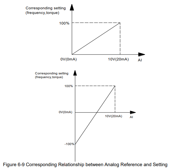
Diagram description (text version): Analog reference to setting: the corresponding setting (frequency, torque) rises linearly from 0% at 0 V (0 mA) to 100% at 10 V (20 mA). Figure 6-9 Corresponding relationship between analog reference and setting: the corresponding setting (frequency, torque) rises linearly from −100% at 0 V (0 mA) to +100% at 10 V (20 mA), crossing 0% in the middle of the input range.
| Parameter | Name | Factory default | Setting range |
|---|---|---|---|
| P4-18 | AI curve 2 minimum input | 0.00V | 0.00V ~ P4-20 |
| P4-19 | AI curve 2 minimum input corresponding setting | 0.0% | -100.00% ~ 100.0% |
| P4-20 | AI curve 2 maximum input | 10.00V | P4-18 ~ 10.00V |
| P4-21 | AI curve 2 maximum input corresponding setting | 100.0% | -100.00% ~ 100.0% |
| P4-22 | AI2 filter time | 0.10s | 0.00s ~ 10.00s |
| Parameter | Name | Factory default | Setting range |
|---|---|---|---|
| P4-23 | AI curve 3 minimum input | 0.00V | -10.00V ~ P4-25 |
| P4-24 | AI curve 3 minimum input corresponding setting | 0.0% | -100.00% ~ 100.0% |
| P4-25 | AI curve 3 maximum input | 10.00V | P4-23 ~ 10.00V |
| P4-26 | AI curve 3 maximum input corresponding setting | 100.0% | -100.00% ~ 100.0% |
| P4-27 | Keypad potentiometer input filter time | 0.10s | 0.00s ~ 10.00s |
| P4-28 | HDI minimum input | 0.00kHz | 0.00kHz ~ P4-30 |
| P4-29 | HDI minimum input corresponding setting | 0.0% | -100.00% ~ 100.0% |
| P4-30 | HDI maximum input | 50.00kHz | P4-28 ~ 100.00kHz |
| P4-31 | HDI maximum input setting | 100.0% | -100.00% ~ 100.0% |
| P4-32 | HDI filter time | 0.10s | 0.00s ~ 10.00s |
This group of function code defines the corresponding relationship when the pulse is used as frequency setting mode.
The pulse frequency input can only be input via HDI channel. The applications of this group function are similar as those of AI curve 1 function.
| Parameter | Name | Factory default | Setting range |
|---|---|---|---|
| P4-33 | AI curve selection | 321 | Units place – AI1 curve selection: 1: Curve 1 (see P4-13 ~ P4-16) 2: Curve 2 (see P4-18 ~ P4-21) 3: Curve 3 (see P4-23 ~ P4-26) Tens place – AI2 curve selection, ibid. |
Units place and tens place of this function code are used to select analog input AI1, AI2 corresponding setting curve.
Curve 1, curve 2, curve 3 are 2 points curves, set by P4 group.
Standard inverter has 2 analog input terminals.
| Parameter | Name | Factory default | Setting range |
|---|---|---|---|
| P4-34 | AI below minimum input setting selection | 000 | Units place – AI1 below minimum input setting selection: 0: Correspond to minimum input setting 1: 0.0% Tens place – AI2 below minimum input setting selection (0 ~ 1, ibid.) Hundreds place – keypad potentiometer below minimum input setting selection (0 ~ 1, ibid.) |
The parameter is used to set how to confirm the analog corresponding setting when the analog input voltage is lower than the setting “the minimum input”.
Units place, tens place and hundreds place of this function code correspond to the analog input AI1, AI2 and Keypad potentiometer.
If the selection is 0, when AI input is lower than “the minimum input”, the analog value corresponding setting is the curve “the minimum input corresponding setting” (P4-14, P4-19, P4-24) determined by the function code.
If the selection is 1, when AI input is lower than “the minimum input”, the analog value corresponding setting is 0.0%.
| Parameter | Name | Factory default | Setting range |
|---|---|---|---|
| P4-35 | DI1 delay time | 0.0s | 0.0s ~ 3600.0s |
| P4-36 | DI2 delay time | 0.0s | 0.0s ~ 3600.0s |
| P4-37 | DI3 delay time | 0.0s | 0.0s ~ 3600.0s |
Used to set the delay time when DI terminal status changing.
Currently only DI1, DI2, DI3 have setting delay time function.
| Parameter | Name | Factory default | Setting range |
|---|---|---|---|
| P4-38 | DI terminal valid mode selection 1 | 00000 | Units place – DI1 terminal valid status setting: 0: Active-high 1: Active-low Tens place – D2 terminal valid status setting (0 ~ 1, ibid.) Hundreds place – D3 terminal valid status setting (0 ~ 1, ibid.) Thousands place – D4 terminal valid status setting (0 ~ 1, ibid.) Ten thousands place – D5 terminal valid status setting (0 ~ 1, ibid.) |
| P4-39 | DI terminal active mode selection 2 | 00 | Units place – D6 terminal valid status setting: 0: Active-high 1: Active-low Tens place – D7/HDI terminal valid status setting (0 ~ 1, ibid.) Hundreds place – D8 terminal valid status setting (0 ~ 1, ibid.) Thousands place – D9 terminal valid status setting (0 ~ 1, ibid.) Ten thousands place – D10 terminal valid status setting (0 ~ 1, ibid.) |
They are used to set the digital input terminal active status mode. If the selection is active-high, the relevant DI terminal connects with COM is valid, disconnect invalid. If the selection is active-high, the relevant DI terminal connects with COM is invalid, disconnect valid.
Słowa kluczowe
Micno KE600, opis parametrów, parameter description, P4, wejścia cyfrowe, digital inputs, DI, D8, D9, D10, HDI, AI1, AI2, krzywa AI, AI curve, sterowanie 3-przewodowe, three-line control
No comments to display
No comments to display