
6. Parameter Description – Part 8 (Groups A2–U0)
Streszczenie: Opis parametrów KE600 (część 8 z 8): parametry silnika 2 (A2: dane silnika, enkoder, pętla prędkości, limit momentu) oraz parametry monitorowania U0.
EN: KE600 parameter description (part 8 of 8): motor 2 parameters (A2: motor data, encoder, speed loop, torque limit) and U0 monitoring parameters.
Dotyczy: falownik wektorowy z zamkniętą pętlą Micno KE600 (zasilanie 3AC 220 V, 3AC 380 V, 3AC 660 V; moce 1,5–630 kW)
Źródło: dokumentacja producenta (Micno KE600 Series Inverter User Manual); tabele przepisane z obrazów na tekst, opisy rysunków – opracowanie Multiprojekt
Nawigacja: część 8 z 8 · poprzednia: ← Part 7 (Groups PB–A0)
Group A2 Motor 2 Parameters
| Parameter | Name | Factory default | Setting range |
|---|---|---|---|
| A2-00 | Motor type | 0 | 0: Common asynchronous motor 1: Variable frequency asynchronous motor |
| A2-01 | Motor rated power | Model dependent | 0.1kW ~ 1000.0kW |
| A2-02 | Motor rated voltage | Model dependent | 1V ~ 2000V |
| A2-03 | Motor rated current | Model dependent | 0.01A ~ 655.35A (inverter power ≤ 55kW) 0.1A ~ 6553.5A (inverter power > 55kW) |
| A2-04 | Motor rated frequency | Model dependent | 0.01Hz ~ P0-10 (maximum frequency) |
| A2-05 | Motor rated speed | Model dependent | 1rpm ~ 65535rpm |
- Please set the parameters correctly according to the motor nameplate.
- In order to achieve superior control performance, please perform motor parameters autotuning. The accuracy of autotuning is closely related to the correct setting of the rated motor parameters.
| Parameter | Name | Factory default | Setting range |
|---|---|---|---|
| A2-06 | Motor stator resistance | Model dependent | 0.001Ω ~ 65.535Ω (inverter power ≤ 55kW) 0.0001Ω ~ 6.5535Ω (inverter power > 55kW) |
| A2-07 | Motor rotor resistance | Model dependent | 0.001Ω ~ 65.535Ω (inverter power ≤ 55kW) 0.0001Ω ~ 6.5535Ω (inverter power > 55kW) |
| A2-08 | Motor leakage inductance | Model dependent | 0.01mH ~ 655.35mH (inverter power ≤ 55kW) 0.001mH ~ 65.535mH (inverter power > 55kW) |
| A2-09 | Motor mutual inductance | Model dependent | 0.1mH ~ 6553.5mH (inverter power ≤ 55kW) 0.01mH ~ 655.35mH (inverter power > 55kW) |
| A2-10 | Motor current without load | Model dependent | 0.01A ~ P1-03 (inverter power ≤ 55kW) 0.1A ~ P1-03 (inverter power > 55kW) |
A2-06 ~ A2-10 are motor parameters, which cannot be found on the motor nameplate, the values are obtained via the inverter autotuning. The static autotuning only can obtain A2-06 ~ A2-08. The rotation autotuning not only can obtain A2-06 ~ A2-10, but also can get current loop PI parameter, etc.
When A2-01 or A2-02 changed, the values of A2-06 ~ A2-10 will be changed automatically, and restore
A2-06 ~ A2-10 as standard Y series motor parameters.
If motor parameters autotuning cannot be performed on the site, please input the related parameters provided by the motor manufacturer.
| Parameter | Name | Factory default | Setting range |
|---|---|---|---|
| A2-11 | Motor parameters autotuning | 0 | 0: No operation 1: Static autotuning 2: Rotation autotuning |
0: No operation, prohibit motor parameter autotuning.
1: Motor parameter static autotuning, suitable for the applications which the asynchronous motor is not easy to disconnect with the load, and cannot make rotation autotuning.
Before performing static autotuning, please set the motor type and motor parameters (A2-00 ~ A2-05) correctly. The inverter can obtain A2-06 ~ A2-08 via static autotuning.
Action description: Set the function code to be 1, the keypad displays “TUNE”, then press RUN key, the inverter will make static autotuning.
2: Motor parameter rotation autotuning
To ensure the dynamic control performance of inverter, please select rotation autotuning. During the rotation autotuning, the motor must be disconnected with the load (i.e. no-load).
During rotation autotuning, the inverter will make static autotuning at first, and then accelerates to 80% motor rated frequency according to acceleration time P0-17, holding for a while, at last decelerates to stop according to deceleration time P0-18 and finish autotuning.
Before rotation autotuning, please set motor type and motor parameters P1-00 ~ P1-05, during rotation autotuning, the inverter can obtain P1-06~P1-10, vector control current loop PI parameters P2-13 ~ P2-16.
Action description: Set the function code to 2, the keypad displays “TUNE”, then press RUN key, the inverter will make rotation autotuning.
Note: Autotuning is valid only on keypad operation mode, cannot make autotuning under terminal and communication operation modes.
| Parameter | Name | Factory default | Setting range |
|---|---|---|---|
| A2-27 | Encoder resolution | 1024 | 0 ~ 10000 |
Set the pulse quantity while the motor run one cycle.
Under the close-loop vector control mode, the encoder resolution has to be set correctly, otherwise, the motor cannot run normally.
| Parameter | Name | Factory default | Setting range |
|---|---|---|---|
| A2-28 | Encoder type | 0 | 0: ABZ incremental encoder |
KE600 is only suitable for ABZ incremental encoder
| Parameter | Name | Factory default | Setting range |
|---|---|---|---|
| A2-30 | Phase-sequence of ABZ incremental encoder | 0 | 0: Forward 1: Reverse |
To set the phase-sequence of encoder A, B signal
| Parameter | Name | Factory default | Setting range |
|---|---|---|---|
| A2-36 | Detection time of PG cables disconnection | 0.0 | 0.0: no detection 0.1 ~ 10.00s |
To set the detection time of encoder cables disconnection, if the set time is 0.0s, the inverter will not detect whether the encoder cable is disconnected or not.
While the encoder cables are disconnected, and after the detection time of A2-36, the inverter will give failure information of “E-20”.
| Parameter | Name | Factory default | Setting range |
|---|---|---|---|
| A2-38 | Speed loop proportional gain 1 | 30 | 1 ~ 100 |
| A2-39 | Speed loop integration time 1 | 0.50s | 0.01s ~ 10.00s |
| A2-40 | Low switching frequency | 5.00Hz | 0.00 ~ P2-05 |
| A2-41 | Speed loop proportional gain 2 | 20 | 1 ~ 100 |
| A2-42 | Speed loop integration time 2 | 1.00s | 0.01s ~ 10.00s |
| A2-43 | High switching frequency | 10.00Hz | P2-02 ~ P0-10 (maximum frequency) |
A2-38 and A2-39 are PI adjustment parameters when the running frequency is lower than low switching frequency (A2-40). A2-41 and A2-42 are PI adjustment parameters when the running frequency is higher than high switching frequency (A2-43). PI parameter of frequency channel between low switching frequency and high switching frequency is linear switching between two groups of PI parameters, as shown in the figure below:
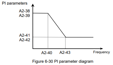
Diagram description (text version): Figure 6-30 PI parameters of motor 2: below the low switching frequency A2-40 the speed loop uses PI parameters A2-38/A2-39; above the high switching frequency A2-43 it uses A2-41/A2-42; between A2-40 and A2-43 the PI parameters change linearly from the first to the second set.
The speed dynamic response characteristics of the vector control can be adjusted by setting the proportional coefficient and integration time of the speed regulator.
Increasing the proportional gain or reducing the integration time can accelerate the dynamic response of the speed loop. However, if the proportional gain is too large or the integration time is too short, it will cause the oscillation of the system.
Recommended adjustment method:
If factory default cannot meet the requirements, the relevant parameter values can be subject to fine tuning. Increase the proportional gain while ensuring no oscillation to the system, and then reduce the integration time to ensure that the system has quick response characteristics and small overshoot.
Caution: Improper PI parameter setting may cause too large speed overshoot. Voltage fault may occur when the overshoot drops.
| Parameter | Name | Factory default | Setting range |
|---|---|---|---|
| A2-44 | Vector control slip compensation coefficient | 100% | 50% ~ 200% |
For sensorless vector control, this parameter is used to adjust the speed stabilizing precision of the motor.
When the speed is too low due to heavy load of motor, this parameter needs to be enlarged, vice versa.
| Parameter | Name | Factory default | Setting range |
|---|---|---|---|
| A2-45 | Speed loop filter time | 0.000s | 0.000s ~ 0.100s |
Under vector control mode, the output of speed loop regulator is torque current command. This parameter is used to filter the torque command. This parameter needs no adjustment generally and this filter time can be increased in case of huge speed fluctuation. In case of oscillation of motor, this parameter should be reduced properly.
The speed loop filter time is low, and the inverter output torque may fluctuate greatly, but the response is quick.
| Parameter | Name | Factory default | Setting range |
|---|---|---|---|
| A2-46 | Vector control over excitation gain | 64 | 0 ~ 200 |
During deceleration, over excitation control can suppress bus voltage increase, avoid over voltage fault.
The bigger over excitation gain is, the better the suppression result is.
For the application which over voltage fault happens frequently during deceleration, the over excitation gain needs to be increased. But the current would be increased if the over excitation is too bigger, so you need to set the suitable over excitation gain.
For the small inertia situation, voltage doesn’t increase during motor deceleration, please set over excitation gain to 0. For the application with braking resistor, please also set over excitation gain to 0.
| Parameter | Name | Factory default | Setting range |
|---|---|---|---|
| A2-47 | Torque upper limit source under speed control mode | 0 | 0: A2-48 1: AI1 2: AI2 3: Keypad potentiometer 4: High speed pulse HDI 5: Communication |
| A2-48 | Torque upper limit digital setting | 150.0% | 0.0% ~ 200.0% |
In the speed control mode, the maximum of the inverter output torque is controlled by the torque upper limit source.
A2-47 is used to select the setting source of torque upper limit. When setting via the analog value, high speed pulse HDI, communication, 100% of the relevant setting corresponds to A2-48, and 100% of A2-48 is the inverter rated torque.
| Parameter | Name | Factory default | Setting range |
|---|---|---|---|
| A2-51 | Proportional gain of excitation regulation | 2000 | 0 ~ 20000 |
| A2-52 | Integral gain of excitation regulation | 1300 | 0 ~ 20000 |
| A2-53 | Proportional gain of torque regulation | 2000 | 0 ~ 20000 |
| A2-54 | Integral gain of torque regulation | 1300 | 0 ~ 20000 |
In the source the second row is labelled “P2-52” (should be A2-52); the parameter list gives the range 0 ~ 6000 for A2-51 … A2-54.
PI regulation parameters of vector control, the parameters will be got automatically after autotunning, in normal condition, they are unnecessary to be modified.
Note: if the PI gain values are set too big, it will cause the control be oscillation, while the current oscillation or torque fluctuation is bigger, the proportional gain and the Integral gain should be decreased manually.
| Parameter | Name | Factory default | Setting range |
|---|---|---|---|
| A2-61 | Control mode (motor 2) | 0 | 0: V/F control 1: Sensorless vector control |
0: V/F control
It is suitable for general purpose application such as pumps, fans etc. One inverter can drive multiple motors.
1: Sensorless vector control
It is widely used for the application which requires high torque at low speed, high speed accuracy, and quicker dynamic response, such as machine tool, injection molding machine, centrifugal machine and wire-drawing machine, etc.
Group U0 Monitoring Parameters
| Code | Name | Range |
|---|---|---|
| U0-00 | Running frequency | 0.00 ~ 320.00Hz (P0-22=2); 0.0 ~ 3200.0Hz (P0-22=1) |
| U0-01 | Setting frequency | 0.00 ~ 320.00Hz (P0-22=2); 0.0 ~ 3200.0Hz (P0-22=1) |
U0-00 displays absolute value of theoretical running frequency of the inverter.
U0-01 displays absolute value of setting frequency of the inverter.
The actual output frequency of inverter refers to U0-19.
| Code | Name | Range |
|---|---|---|
| U0-02 | DC bus voltage | 0.0V ~ 3000.0V |
U0-02 displays the voltage of DC bus.
| Code | Name | Range |
|---|---|---|
| U0-03 | Output voltage | 0V ~ 1140V |
U0-03 displays the output voltage of inverter at run time.
| Code | Name | Range |
|---|---|---|
| U0-04 | Output current | 0.00A ~ 655.35A (rated power ≤ 55kW); 0.0A ~ 6553.5A (rated power > 55kW) |
U0-04 displays the output current of inverter at run time.
| Code | Name | Range |
|---|---|---|
| U0-05 | Output power | 0 ~ 32767 |
U0-05 displays the output power of inverter at run time.
| Code | Name | Range |
|---|---|---|
| U0-06 | Output torque | -200.0% ~ 200.0% |
U0-06 displays the output torque of inverter at run time.
| Code | Name | Range |
|---|---|---|
| U0-07 | DI input status | 0 ~ 32767 |
U0-07 displays the digital value Input terminal state which can be expressed by a 8-bit binary code; if the inverter detects that the input of corresponding terminal is high level(closed), then this bit is set to "1", if the input of corresponding terminal is low level(open), then the bit is set to "0". The relationship between Digital value Input terminal and binary code is shown below.
U0-07 – DI input status bits
| Bit | Signal |
|---|---|
| Bit0 | DI1 |
| Bit1 | DI2 |
| Bit2 | DI3 |
| Bit3 | DI4 |
| Bit4 | DI5 |
| Bit5 | DI6 |
| Bit6 | DI7 |
| Bit7 | – |
| Code | Name | Range |
|---|---|---|
| U0-08 | DO output status | 0 ~ 1023 |
U0-07 displays the digital value output terminal state which can be expressed by a 8-bit binary code; if the inverter detects that the output of corresponding terminal is high level (closed), then this bit is set to "1", if the output of corresponding terminal is low level (open), then the bit is set to "0". The relationship between Digital value output terminal and binary code is shown below
U0-08 – DO output status bits
| Bit | Signal |
|---|---|
| Bit0 | DO3 |
| Bit1 | Relay 1 |
| Bit2 | Relay 2 |
| Bit3 | DO1 |
| Bit4 | DO2 |
| Bit5 | – |
| Bit6 | – |
| Bit7 | – |
| Code | Name | Range |
|---|---|---|
| U0-09 | AI1 voltage | -10 ~ 10V |
U0-09 displays the input voltage of AI1.
| Code | Name | Range |
|---|---|---|
| U0-10 | AI2 voltage | -10 ~ 10V |
U0-10 displays the input voltage of AI2
| Code | Name | Range |
|---|---|---|
| U0-11 | Radiator temperature | -20 ~ 100 °C |
U0-11 displays the current temperature of radiator
| Code | Name | Range |
|---|---|---|
| U0-12 | Count value | – |
U0-12 displays the current value of counter.
| Code | Name | Range |
|---|---|---|
| U0-13 | Length value | – |
U0-13 displays the current value of length.
| Code | Name | Range |
|---|---|---|
| U0-14 | Load speed | 0 ~ 65535 |
U0-14 displays the speed of load. Refer to the description of P7-12 in user manual.
| Code | Name | Range |
|---|---|---|
| U0-15 | PID setting | 0 ~ 65535 |
| U0-16 | PID feedback | 0 ~ 65535 |
U0-15 displays the setting value of PID.
U0-16 displays the feedback value of PID.
Take the following formulas as follows:
The setting value of PID= the setting (percentage) of PID × PA-04
The feedback value of PID=the feedback (percentage) of PID × PA-04
| Code | Name | Range |
|---|---|---|
| U0-17 | PLC phase | 0 ~ F |
U0-14 displays the current step when inverter is running in simple PLC mode.
The relationship between displayed value and current step is shown below.
U0-17 – PLC phase display
| Displayed value | Inverter is running at step X |
|---|---|
| 1 | X: 0 |
| 2 | X: 1 |
| …… | …… |
| F | X: 15 |
| Code | Name | Range |
|---|---|---|
| U0-18 | HDI input pulse frequency | 0.00 ~ 100.0kHz |
U0-18 displays the sampling frequency of High-speed-pulse input (HDI). The smallest unit is 0.01 KHz.
| Code | Name | Range |
|---|---|---|
| U0-19 | Feedback speed | -320.00 ~ 320.00Hz; -3200.0 ~ 3200.0Hz |
U0-19 displays the actual output frequency of inverter:
When P0-22 is set to 1, the range is -3200.0 to 3200.0. (Unit: Hz)
When P0-22 is set to 2, the range is -320.00 to 320.00. (Unit: Hz)
| Code | Name | Range |
|---|---|---|
| U0-20 | Remain running time | 0.0 ~ 6500.0min |
U0-20 displays remain running time when inverter is running at timing running mode. (Refer to P8-42, P8-43 and P8-44).
| Code | Name | Range |
|---|---|---|
| U0-21 | AI1 voltage before calibration | 0.00 ~ 10.57V |
| U0-22 | AI2 voltage before calibration | 0.00 ~ 10.57V |
| U0-23 | Keypad potentiometer voltage before calibration | 0.00 ~ 10.57V |
U0-21 displays the sampling voltage of analog input 1(AI1).
U0-22 displays the sampling voltage of analog input 2(AI2).
The actual input voltage is corrected value after linear calibration, so as to reduce the deviation between sampling voltage and the actual input voltage.
U0-09 and U0-10 display the actual voltages.
| Code | Name | Range |
|---|---|---|
| U0-24 | Linear velocity | 0 ~ 65535 m/min |
U0-24 displays the sampling linear velocity of High-speed-pulse input (HDI). The unit is meter per minute (m/min).
It can be calculated according to number of the actual sampling pulse and PB-07(number of pulse per meter).
| Code | Name | Range |
|---|---|---|
| U0-27 | HDI input pulse frequency | 0 ~ 65535Hz |
U0-27 displays the sampling frequency of High-speed-pulse input (HDI). The unit is 1 Hz. Actually, U0-27 displays the same data with U0-18. The only difference is the unit.
| Code | Name | Range |
|---|---|---|
| U0-28 | Communication setting value | -100 ~ 100% |
U0-28 displays the data written to address 0X1000.
| Code | Name | Range |
|---|---|---|
| U0-29 | Encoder feedback frequency | – |
| Code | Name | Range |
|---|---|---|
| U0-30 | Main frequency A display | 0.00 ~ 320.00Hz |
U0-30 displays the frequency of main reference-input-channel (Refer to P0-03).
When P0-22 is set to 1, the range is -3200.0 to 3200.0 (Unit: Hz).
When P0-22 is set to 2, the range is -320.00 to 320.00 (Unit: Hz).
| Code | Name | Range |
|---|---|---|
| U0-31 | Auxiliary frequency B display | 0.00 ~ 320.00Hz |
U0-31 displays the frequency of auxiliary reference-input-channel (Refer to P0-04).
When P0-22 is set to 1, the range is -3200.0 to 3200.0 (Unit: Hz).
When P0-22 is set to 2, the range is -320.00 to 320.00 (Unit: Hz).
| Code | Name | Range |
|---|---|---|
| U0-32 | Reserved | – |
| U0-33 | Reserved | – |
| Code | Name | Range |
|---|---|---|
| U0-34 | Motor temperature | 0 ~ 200 °C |
U0-43 displays the current temperature of motor.
NOTE: This code is reserved (not available in present).
| Code | Name | Range |
|---|---|---|
| U0-35 | Target torque | -200 ~ 200% |
U0-43 displays the current upper limit setting of torque. Refer to P2-09 and P2-10.
| Code | Name | Range |
|---|---|---|
| U0-36 | Reserved | – |
| Code | Name | Range |
|---|---|---|
| U0-37 | Power factor angle | – |
U0-43 displays the current power factor angle.
| Code | Name | Range |
|---|---|---|
| U0-38 | ABZ position | – |
| Code | Name | Range |
|---|---|---|
| U0-39 | Reserved | – |
| U0-40 | Reserved | – |
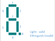
Diagram description (text version): Segment numbering of one LED digit used by the status visual displays U0-41/U0-42: segments 1 (top), 2 (upper right), 3 (lower right), 4 (bottom), 5 (lower left), 6 (upper left), 7 (middle) and 8 (decimal point); a lit segment means valid, an extinguished segment means invalid.
| Code | Name | Range |
|---|---|---|
| U0-41 | Input status visual display | – |
U0-41 displays the input terminal state on the keypad intuitively.
Take the description for reference:
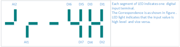
Diagram description (text version): U0-41 input status visual display: each segment of the 7-segment LED display (segments 1–8 of a digit; lit = valid, off = invalid) shows one digital input. In the example display the segments are assigned to AI2, AI1, DI6, DI5, DI3, DI1 (upper segments) and DI7, DI4, DI2 (lower segments); a lit segment means the input is at high level, and vice versa.
| Code | Name | Range |
|---|---|---|
| U0-42 | DO input status visual display | – |
U0-42 displays the digital value output terminal state on the keypad intuitively.
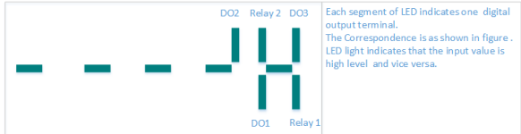
Diagram description (text version): U0-42 output status visual display: each LED segment indicates one digital output – DO2, Relay 2 and DO3 (upper segments) and DO1 and Relay 1 (lower segments); a lit segment means the output is at high level, and vice versa.
| Code | Name | Range |
|---|---|---|
| U0-43 | DO input status visual display 1 | – |
U0-43 displays whether intuitive display function 1-40 are valid or not.
There are 5 digital tubes on keypad. Every digital tube has 8 segments, and each segment indicates a certain function selection.
Define digital tube as shown in figure.
Digital tubes from left to right represent intuitive display function 1-8, 9-16, 7-24, 25-32, 33-40.
| Code | Name | Range |
|---|---|---|
| U0-44 | DI input status visual display 2 | – |
U0-44 displays whether intuitive display function 41-59 are valid or not.
There are 5 digital tubes on keypad. Every digital tube has 8 segments, and each segment indicates a certain function selection. Digital tubes from left to right represent intuitive display function 41-48, 49-56, 57-59.
NOTE: U0-33 and U0-34 are testing codes for manufacturers
| Code | Name | Range |
|---|---|---|
| U0-45 … U0-58 | Reserved | – |
| Code | Name | Range |
|---|---|---|
| U0-59 | Setting frequency | -100% ~ 100% |
| U0-60 | Running frequency | -100% ~ 100% |
U0-59 displays current setting frequency.
U0-60 displays current running frequency.
100% is corresponding to Max. frequency (P0-10).
| Code | Name | Range |
|---|---|---|
| U0-61 | Inverter status | 0 ~ 65535 |
U0-61 displays information of inverter running status. Take the following as reference.
U0-61 – inverter status bits
| Bits | Meaning |
|---|---|
| Bit 0 & bit 1 | 0: stop; 1: forward; 2: reverse |
| Bit 2 & bit 3 | 0: constant speed; 1: acceleration; 2: deceleration |
| Bit 4 | 0: the voltage of DC bus is normal; 1: under voltage |
NOTE: A digital tube is corresponding to one bit above.
Słowa kluczowe
Micno KE600, opis parametrów, parameter description, A2, silnik 2, motor 2, U0, monitorowanie, monitoring, U0-61, status falownika, inverter status, wizualizacja DI/DO
No comments to display
No comments to display