
2. Interface and Indicator
Streszczenie: Definicja pinów 12-pinowego złącza M12 czytnika ID5000 (zasilanie, wyjścia OPTO_OUT0–2, wejścia OPTO_IN0–2, wspólne masy, RS-232, kolory przewodów) oraz stany wskaźników PWR, LNK, ACT i U1/U2 przy pracy normalnej i błędach.
EN: ID5000 12-pin M12 interface pin definitions (power, OPTO_OUT0–2 outputs, OPTO_IN0–2 inputs, common grounds, RS-232, wire colours) and PWR, LNK, ACT and U1/U2 indicator status in normal operation and on errors.
Dotyczy: przemysłowy czytnik kodów Hikrobot serii ID5000 (złącze M12 12-pin, Gigabit Ethernet, RS-232; obsługa przez klienta IDMVS)
Źródło: dokumentacja producenta (Hikrobot ID5000 Series Industrial Code Reader User Manual, V2.5.0); tabele i uwagi przepisane z obrazów na tekst; opisy rysunków – opracowanie Multiprojekt
2.1 12-Pin Interface
Read the following section to get definitions of 12-pin interface.
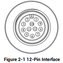
Figure 2-1 12-Pin Interface
Figure description (text version): Front view of the 12-pin M12 connector with the coding key at the top. Pins 1–9 are arranged around the outer ring (starting at the top right, counter-clockwise), pins 10, 11 and 12 are in the centre.
Table 2-1 Pin Definitions
| No. | Signal | I/O Signal Source | Description | Color |
|---|---|---|---|---|
| 1 | DC-PWR | – | Direct current power supply positive | White |
| 2 | GND | – | Power supply ground | Brown |
| 3 | OPTO_OUT0 | LineOut0 signal line | Opto-isolated output 0 | Green |
| 4 | OPTO_OUT1 | LineOut1 signal line | Opto-isolated output 1 | Yellow |
| 5 | OPTO_OUT2 | LineOut2 signal line | Opto-isolated output 2 | Gray |
| 6 | OUT_COM | LineOut0/1/2 signal ground | Common-ended output | Pink |
| 7 | OPTO_IN0 | LineIn0 signal line | Opto-isolated input 0 | Blue |
| 8 | OPTO_IN1 | LineIn1 signal line | Opto-isolated input 1 | Red |
| 9 | OPTO_IN2 | LineIn2 signal line | Opto-isolated input 2 | Black |
| 10 | IN_COM | LineIn0/1/2 signal ground | Common-ended input | Purple |
| 11 | RS232_R | – | RS232 serial port input | Gray/Pink |
| 12 | RS232_T | – | RS232 serial port output | Red/Blue |
Note: You should refer to the table above and the label attached to the power and I/O cable to wire the device.
2.2 Indicator Status
Read the following section to get the indicator status of the device.
Table 2-2 Description
| Device Status | PWR Indicator | LNK Indicator | ACT Indicator | U1/U2 |
|---|---|---|---|---|
| Device is powered on. | Solid blue | Solid green | Slow/fast flashing yellow | U1 is unlit, and U2 is slow flashing blue. |
| Power supply exception. | Unlit | Unlit | Unlit | Unlit |
| Network exception. | Solid blue | Unlit | Unlit | U1 is unlit, and U2 is slow flashing blue. |
| Device software exception. | Solid blue | Solid green | Flashing yellow | U1 and U2 are unlit. |
| Device exception | Solid blue | Solid green | Solid yellow | U1 and U2 are solid blue. |
Note: When the indicators are flashing slowly, their unlit interval is 1 s.
Słowa kluczowe
Hikrobot ID5000, 12-pin, M12, pinout, pin definitions, DC-PWR, GND, OPTO_OUT0, OPTO_OUT1, OPTO_OUT2, OUT_COM, OPTO_IN0, OPTO_IN1, OPTO_IN2, IN_COM, RS232, wire color, indicator status, PWR, LNK, ACT, U1/U2, wskaźniki
No comments to display
No comments to display