
4. Installation
Streszczenie: Instalacja czytnika ID5000: akcesoria (kabel zasilania i I/O 12-pin, kabel sieciowy GigE, zasilacz 24 VDC, obiektyw C-mount, oświetlenie, wspornik), montaż tylny lub przedni oraz podłączenie sieci i zasilania.
EN: ID5000 installation: accessories (12-pin power and I/O cable, GigE network cable, 24 VDC power supply, C-mount lens, light source, bracket), rear or front mounting and network/power connection.
Dotyczy: przemysłowy czytnik kodów Hikrobot serii ID5000 (złącze M12 12-pin, Gigabit Ethernet, RS-232; obsługa przez klienta IDMVS)
Źródło: dokumentacja producenta (Hikrobot ID5000 Series Industrial Code Reader User Manual, V2.5.0); tabele i uwagi przepisane z obrazów na tekst; opisy rysunków – opracowanie Multiprojekt
4.1 Installation Preparation
You need to prepare following accessories before installation.
Table 4-1 Accessories
| No. | Name | Quantity | Description |
|---|---|---|---|
| 1 | Power and I/O Cable | 1 | It refers to the 3-meter 12-pin power and I/O cable, and is included in the package. |
| 2 | Network Cable | 1 | It refers to the 3-meter GigE network cable with RJ45 connector and aviation connector. It is included in the package. |
| 3 | DC Switch Power Supply | 1 | It refers to DC switch power supply of 24 VDC and above 1A/2A. Refer to the specification of the device for detailed power supply information. You need to purchase separately. |
| 4 | Lens | 1 | It refers to C-mount lens that you need to purchase it separately. The C-mount lens is used for the type III device. Note: the type II device is equipped with M12-mount lens. |
| 5 | Light Source | 1 | It is used to provide light during image acquisition. You need to purchase separately. |
| 6 | Fixed Bracket | 1 | It is used to fix the device. You need to purchase separately. |
| 7 | M4 Screw | 4 | It refers to the supplied M4 screw that is used to fix the device to installation position. |
4.2 Install Device
Before You Start
- Make sure the device in the package is in good condition and all the assembly parts are included.
- Make sure that all the related devices are powered off during the installation.
Note: Here the type I device is taken as an example to introduce installation.
Steps
- Use M4 screw to fix the device to fixed bracket.
- Select one of installation methods, and install the device to the installation position.
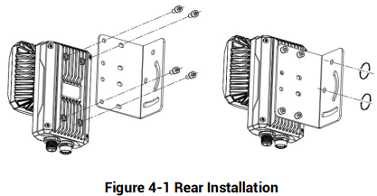
Figure 4-1 Rear Installation
Figure description (text version): Mounting drawing: an angle bracket is fixed with four M4 screws to the rear (heat-sink side) of the device; the bracket is then fixed to the installation position through its slotted holes.
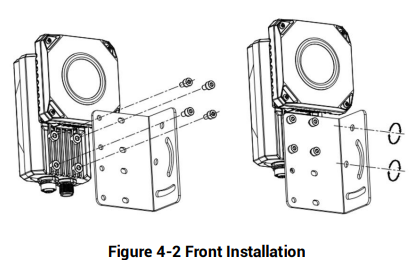
Figure 4-2 Front Installation
Figure description (text version): Mounting drawing: the angle bracket is fixed with four M4 screws to the front part of the housing below the lens cap; the bracket is then fixed to the installation position through its slotted holes.
- Use GigE network cable with RJ45 aviation connector to connect the device to a switch or a network interface card.
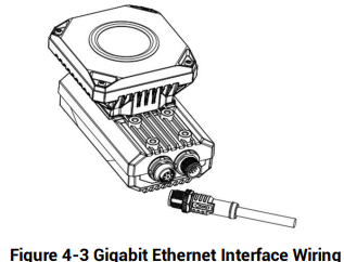
Figure 4-3 Gigabit Ethernet Interface Wiring
Figure description (text version): Drawing: the screw-locking connector of the network cable being plugged into the Gigabit Ethernet interface on the bottom of the device.
- Use power and I/O cable to connect the device to a DC switch power supply
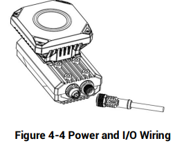
Figure 4-4 Power and I/O Wiring
Figure description (text version): Drawing: the screw-locking M12 connector of the power and I/O cable being plugged into the 12-pin interface on the bottom of the device.
Słowa kluczowe
Hikrobot ID5000, installation, instalacja, montaż, accessories, power and I/O cable, GigE network cable, RJ45, aviation connector, DC power supply, C-mount lens, fixed bracket, M4 screw, rear installation, front installation
No comments to display
No comments to display