
8. Device Settings – Part 3 (Signal Input, Output and Indicator)
Streszczenie: Ustawienia ID5000 cz. 3: wyzwalanie wewnętrzne i zewnętrzne (programowe, sprzętowe, licznik, TCP, UDP, port szeregowy, self trigger), zatrzymanie wyzwalania, wybór wyjścia, inwersja, źródła zdarzeń wyjść LineOut oraz konfiguracja wskaźników U1/U2.
EN: ID5000 settings part 3: internal and external trigger (software, hardware, counter, TCP, UDP, serial, self trigger), stop trigger, output selection, line inverter, LineOut event sources and U1/U2 indicator customization.
Dotyczy: przemysłowy czytnik kodów Hikrobot serii ID5000 (złącze M12 12-pin, Gigabit Ethernet, RS-232; obsługa przez klienta IDMVS)
Źródło: dokumentacja producenta (Hikrobot ID5000 Series Industrial Code Reader User Manual, V2.5.0); tabele i uwagi przepisane z obrazów na tekst; opisy rysunków – opracowanie Multiprojekt
Rozdział 8 „Device Settings” – części: Part 1 – Image Quality | Part 2 – Code Algorithm | Part 3 – Signal Input, Output and Indicator | Part 4 – Code Reading Result and Contrast Control | Part 5 – Communication, User Set, Statistics, Events
← poprzednia część · następna część →
8.3 Signal Input Settings
In the signal input module, you can set the trigger related parameters. You can enable trigger mode to let the acquisition of image data occur only when the trigger source is generated.
8.3.1 Set Trigger Mode
The device has 2 types of trigger modes, including internal trigger mode and external trigger mode.
Internal Trigger Mode
In this mode, the device acquires images via its internal signals.
External Trigger Mode
In this mode, the device acquires images via external signals like software signal and hardware signal. The trigger source of external trigger mode includes software, physical lines, counter, TCP, UDP, serial port and self trigger.
Note: The specific external trigger mode may differ by device models.
8.3.2 Enable Internal Trigger Mode
In the internal trigger mode, the device acquires images via its internal signals. You have 2 methods to enable the internal trigger mode:
- Click I/O Control Settings → Input → Trigger Mode, and select Off as Trigger Mode.
- In the live view page, click to enable the internal trigger mode.
8.3.3 Enable External Trigger Mode
In the external trigger mode, the device acquires images via external signals like software signal and hardware signal. You have 2 methods to enable the external trigger mode:
- Click I/O Control Settings → Input → Trigger Mode, and select On as Trigger Mode.
- In the live view page, click to enable the external trigger mode.
Set and Execute Software Trigger Mode
In software trigger, the software sends trigger signal to the device via I/O interface to acquire images.
Steps
- Click I/O Control Settings → Input → Trigger Mode.
- Select On as Trigger Mode.
- Select Software as Trigger Source.
- Click Execute in Trigger Source to send trigger commands.
You can also enter Auto Trigger Time, and then enable Enable Auto Trigger to let the client software automatically send trigger signal to device according to the interval you set.
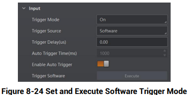
Figure 8-24 Set and Execute Software Trigger Mode
Figure description (text version): Input group: Trigger Mode On, Trigger Source Software, Trigger Delay (us) 0.00, Auto Trigger Time (ms) 1000 (greyed), Enable Auto Trigger switched on, Trigger Software Execute button.
Set and Execute Hardware Trigger Mode
This heading is missing in the source document and has been reconstructed from the steps and figure below.
Steps
- Click I/O Control Settings → Input → Trigger Mode.
- Select On as Trigger Mode.
- Select the specific line as Trigger Source according to actual demands.
- Set Debounce Time and Line Out Trigger In Polarity according to actual demands.
Note:
- When selecting Rising Edge or Falling Edge as Line Out Trigger In Polarity, you can set Trigger Delay.
- When selecting Level High or Level Low as Line Out Trigger In Polarity, you can set Start Delay Time and End Delay Time according to actual demands.
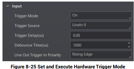
Figure 8-25 Set and Execute Hardware Trigger Mode
Figure description (text version): Input group: Trigger Mode On, Trigger Source LineIn 0, Trigger Delay (us) 0.00, Debounce Time (us) 1000, Line Out Trigger In Polarity Rising Edge.
Set and Execute Counter Trigger Mode
Counter specifies that the trigger source will be generated after the set number of valid signals appears. For example, if you set the Count Number to 3, the trigger source will be generated after 3 signals appear.
Steps
- Click I/O Control Settings → Input → Trigger Mode.
- Select On as Trigger Mode.
- Select Counter 0 as Trigger Source.
- Set Trigger Delay, Count Number, Count Source and Line Out Trigger In Polarity according to actual demands.
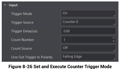
Figure 8-26 Set and Execute Counter Trigger Mode
Figure description (text version): Input group: Trigger Mode On, Trigger Source Counter 0, Trigger Delay (us) 0.00, Count Number 1, Count Source Off, Line Out Trigger In Polarity Falling Edge.
Set and Execute TCP Trigger Mode
TCP start specifies the TCP server as the source for the trigger signal. When the server receives the specified string text, the trigger signal will be outputted.
Steps
- Click I/O Control Settings → Input → Trigger Mode.
- Select On as Trigger Mode.
- Select TCP Start as Trigger Source.
- Set Trigger Delay, TCP Trigger Port, and TCP Start Trigger Text according to actual demands.
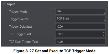
Figure 8-27 Set and Execute TCP Trigger Mode
Figure description (text version): Input group: Trigger Mode On, Trigger Source TCP Start, Trigger Delay (us) 0.00, TCP Trigger Port 2001, TCP Start Trigger Text "start".
Set and Execute UDP Trigger Mode
UDP start specifies the UDP server as the source for the trigger signal. When the server receives the specified string text, the trigger signal will be outputted.
Steps
- Click I/O Control Settings → Input → Trigger Mode.
- Select On as Trigger Mode.
- Select UDP Start as Trigger Source.
- Set Trigger Delay, UDP Trigger Port, and UDP Start Trigger Text according to actual demands.
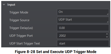
Figure 8-28 Set and Execute UDP Trigger Mode
Figure description (text version): Input group: Trigger Mode On, Trigger Source UDP Start, Trigger Delay (us) 0.00, UDP Trigger Port 2002, UDP Start Trigger Text "start".
Set and Execute Serial Port Trigger Mode
Serial start specifies the serial port as the source for the trigger signal. When the serial port receives the specified string text, the trigger signal will be outputted.
Steps
- Click I/O Control Settings → Input → Trigger Mode.
- Select On as Trigger Mode.
- Select Serial Start as Trigger Source.
- Set Trigger Delay, Serial Baud Rate, Serial Data Bits, Serial Parity, Serial Stop Bits, and Serial Start Trigger Text according to actual demands.
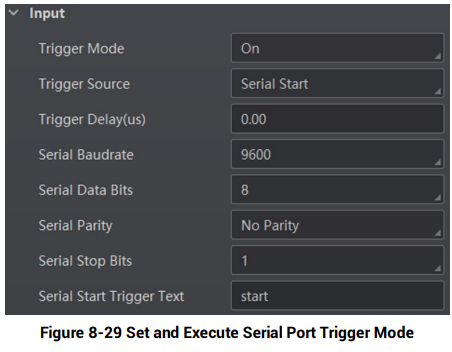
Figure 8-29 Set and Execute Serial Port Trigger Mode
Figure description (text version): Input group: Trigger Mode On, Trigger Source Serial Start, Trigger Delay (us) 0.00, Serial Baudrate 9600, Serial Data Bits 8, Serial Parity No Parity, Serial Stop Bits 1, Serial Start Trigger Text "start".
Set and Execute Self Trigger Mode
Self trigger mode allows you to trigger the device according to the trigger period you configured.
Steps
- Click I/O Control Settings → Input → Trigger Mode.
- Select On as Trigger Mode.
- Select Self Trigger as Trigger Source, and set Self Trigger Period and Self Trigger Count.
- Click Execute in Self Trigger Start to start, and click Execute in Self Trigger Stop to stop.
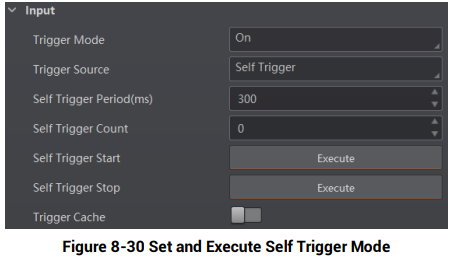
Figure 8-30 Set and Execute Self Trigger Mode
Figure description (text version): Input group: Trigger Mode On, Trigger Source Self Trigger, Self Trigger Period (ms) 300, Self Trigger Count 0, Self Trigger Start (Execute), Self Trigger Stop (Execute), Trigger Cache off.
8.3.4 Stop Trigger
Stop trigger settings configure the source and condition to stop trigger. You can stop device trigger via TCP, UDP, I/O and serial port.
TCP Stop Trigger
When the TCP server receives the specified string text, the trigger will be stopped. Click I/O Control Settings → Stop Trigger, enable Tcp Stop Trigger Enable, set Tcp Trigger Port and Tcp Stop Trigger Text according to actual demands.
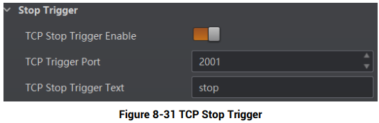
Figure 8-31 TCP Stop Trigger
Figure description (text version): Stop Trigger group: TCP Stop Trigger Enable on, TCP Trigger Port 2001, TCP Stop Trigger Text "stop".
UDP Stop Trigger
When the UDP server receives the specified string text, the trigger will be stopped. Click I/O Control Settings → Stop Trigger, enable Udp Stop Trigger Enable, set Udp Trigger Port and Udp Stop Trigger Text according to actual demands.
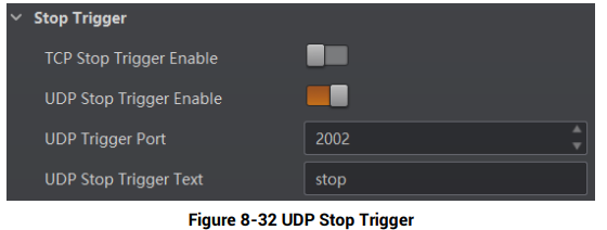
Figure 8-32 UDP Stop Trigger
Figure description (text version): Stop Trigger group: TCP Stop Trigger Enable off, UDP Stop Trigger Enable on, UDP Trigger Port 2002, UDP Stop Trigger Text "stop".
IO Stop Trigger
You can select the physical line or software from IO Stop Trigger Selector as the source to stop trigger, and set the Rising Edge or Falling Edge as the condition to stop trigger. Click I/O Control Settings → Stop Trigger, enable IO Stop Trigger Enable, and set LineIn 0, LineIn 1, LineIn 2 or Software Trigger End as IO Stop Trigger Selector.
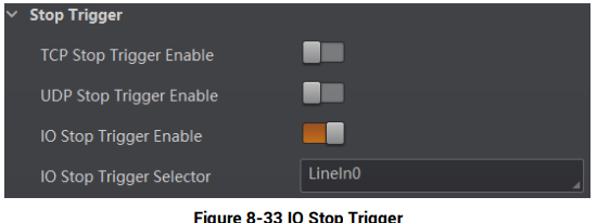
Figure 8-33 IO Stop Trigger
Figure description (text version): Stop Trigger group: TCP Stop Trigger Enable off, UDP Stop Trigger Enable off, IO Stop Trigger Enable on, IO Stop Trigger Selector LineIn0.
When selecting Software Trigger End as IO Stop Trigger Selector, you can click Execute in Software Stop Trigger to stop current trigger.
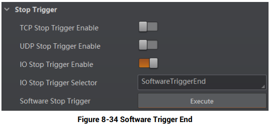
Figure 8-34 Software Trigger End
Figure description (text version): Stop Trigger group: TCP and UDP Stop Trigger Enable off, IO Stop Trigger Enable on, IO Stop Trigger Selector SoftwareTriggerEnd, Software Stop Trigger (Execute).
Serial Stop Trigger
When the specified serial port receives the specified string text, the trigger will be stopped. Click I/O Control Settings → Stop Trigger, enable Serial Stop Trigger Enable, set Serial Stop Trigger Text, Serial Baud Rate, Serial Data Bits, Serial parity, and Serial Stop Bits according to actual demands.
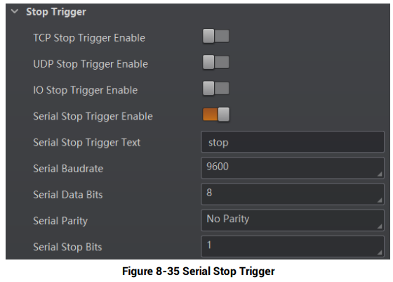
Figure 8-35 Serial Stop Trigger
Figure description (text version): Stop Trigger group: TCP, UDP and IO Stop Trigger Enable off, Serial Stop Trigger Enable on, Serial Stop Trigger Text "stop", Serial Baudrate 9600, Serial Data Bits 8, Serial Parity No Parity, Serial Stop Bits 1.
Stop Trigger via Timeout Duration
Note: TimeOut Stop Trigger Enable is only available when the device mode is set to Normal and the Trigger Mode is On.
When the trigger time reaches the specified maximum value (in ms), the trigger will be stopped. You can enable TimeOut Stop Trigger Enable, and set Maximum Output Limited Time according to actual demands.

Figure 8-36 Stop Trigger via Timeout Duration
Figure description (text version): Parameters: TimeOut Stop Trigger Enable on, Maximum Output Limited Time (ms) 5000.
8.4 Signal Output Settings
8.4.1 Select Output Signal
The device’s output signal can control external devices like PLC, flashing light, etc. Click I/O Control Settings → Output → Line Out Selector to select output signal.
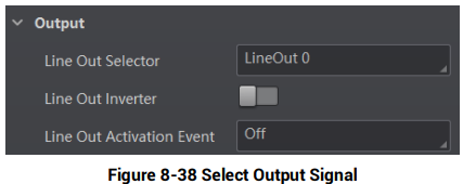
Figure 8-38 Select Output Signal
Figure description (text version): Output group: Line Out Selector LineOut 0, Line Out Inverter off, Line Out Activation Event Off.
8.4.2 Enable Line Inverter
The level inverter function allows the device to invert the electrical signal level of an I/O line, and meets requirements of different devices for high or low electrical signal level.
You can go to I/O Control Settings → Output → Line Out Inverter to enable it.
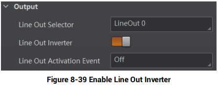
Figure 8-39 Enable Line Out Inverter
Figure description (text version): Output group: Line Out Selector LineOut 0, Line Out Inverter on, Line Out Activation Event Off.
8.4.3 Set Event Source
The device supports outputting different trigger signals according to the event source you select.
Click I/O Control Settings → Output → Line Out Activation Event to select event source. The device supports following event sources, including Acquisition Start Active, Acquisition Stop Active, Frame Burst Start Active, Frame Burst Stop Active, Exposure Start Active, Soft Trigger Active, Hard Trigger Active, Counter Active, Timer Active, No Code Read, Read Success, and Light Strobe Long, Compare Success, and Compare Fail.
Note:
- Off refers to no event source.
- Some event sources support the function of trigger output cache, and you can go to Feature Tree → Trigger and IO Control > Line Out Cache to enable it.
Acquisition Start Active
If acquisition starts, the output signal will be triggered.
Acquisition Stop Active
If acquisition stops, the output signal will be triggered.
Frame Burst Start Active
If the burst of a frame starts, the output signal will be triggered.
Frame Burst Stop Active
If the burst of a frame stops, the output signal will be triggered.
Exposure Start Active
If the exposure starts, the output signal will be triggered.
Soft Trigger Active
The client software triggers the output signal.
Hard Trigger Active
The external signals trigger the output signal.
Counter Active
Trigger the output signal by the counter.
Timer Active
The timer triggers the output signal.
No Code Read
If no code read by the device, the output signal will be triggered.
Read Success
If the code is read by the device, the output signal will be triggered.
Light Strobe Long
If the light mode is Strobe Long, the output signal will be triggered.
Compare Success
If data comparison is successful, the output signal will be triggered.
Compare Fail
If data comparison is failed, the output signal will be triggered.
Note: You need to set different parameters when selecting these event sources.
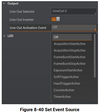
Figure 8-40 Set Event Source
Figure description (text version): Output group (with an LED group below) with the Line Out Activation Event list expanded: Off, AcquisitionStartActive, AcquisitionStopActive, FrameBurstStartActive, FrameBurstStopActive, ExposureStartActive, SoftTriggerActive, HardTriggerActive, CounterActive, TimerActive (list continues).
Select Acquisition Start Active
If you select Acquisition Start Active as Line Out Activation Event, you can set its output delay time and duration.
Line Out Delay Time
It sets the delay time for outputting the output signal.
Line Out Duration
It sets the time duration of the output signal.
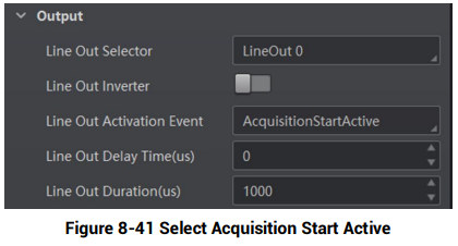
Figure 8-41 Select Acquisition Start Active
Figure description (text version): Output group: Line Out Selector LineOut 0, Line Out Inverter off, Line Out Activation Event AcquisitionStartActive, Line Out Delay Time (us) 0, Line Out Duration (us) 1000.
Select Acquisition Stop Active
If you select Acquisition Stop Active as Line Out Activation Event, you can set its output delay time and duration.
Line Out Delay Time
It sets the delay time for outputting the output signal.
Line Out Duration
It sets the time duration of the output signal.
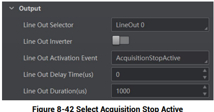
Figure 8-42 Select Acquisition Stop Active
Figure description (text version): Output group: Line Out Selector LineOut 0, Line Out Inverter off, Line Out Activation Event AcquisitionStopActive, Line Out Delay Time (us) 0, Line Out Duration (us) 1000.
Select Frame Burst Start Active
If you select Frame Burst Start Active as Line Out Activation Event, you can set its output delay time and duration.
Line Out Delay Time
It sets the delay time for outputting the output signal.
Line Out Duration
It sets the time duration of the output signal.
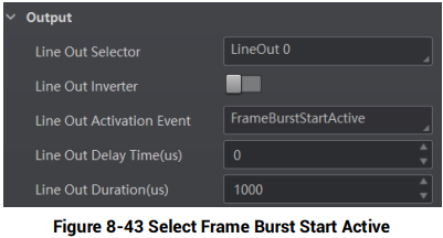
Figure 8-43 Select Frame Burst Start Active
Figure description (text version): Output group: Line Out Selector LineOut 0, Line Out Inverter off, Line Out Activation Event Frame Burst Start Active, Line Out Delay Time (us) 0, Line Out Duration (us) 1000.
Select Frame Burst Stop Active
If you select Frame Burst Stop Active as Line Out Activation Event, you can set its output delay time and duration.
Line Out Delay Time
It sets the delay time for outputting the output signal.
Line Out Duration
It sets the time duration of the output signal.
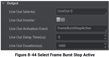
Figure 8-44 Select Frame Burst Stop Active
Figure description (text version): Output group: Line Out Selector LineOut 0, Line Out Inverter off, Line Out Activation Event FrameBurstStopActive, Line Out Delay Time (us) 0, Line Out Duration (us) 1000.
Select Exposure Start Active
If you select Exposure Start Active as Line Out Activation Event, you can set its output delay time and duration.
Line Out Delay Time
It sets the delay time for outputting the output signal.
Line Out Duration
It sets the time duration of the output signal.
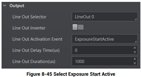
Figure 8-45 Select Exposure Start Active
Figure description (text version): Output group: Line Out Selector LineOut 0, Line Out Inverter off, Line Out Activation Event ExposureStartActive, Line Out Delay Time (us) 0, Line Out Duration (us) 1000.
Select Soft Trigger Active
If you select Soft Trigger Active as Line Out Activation Event, you can set its output delay time, duration, and execute outputting signal manually.
Line Out Delay Time
It sets the delay time for outputting the output signal.
Line Out Duration
It sets the time duration of the output signal.
Line Trigger Software
Click Execute for manually outputting the output signal.
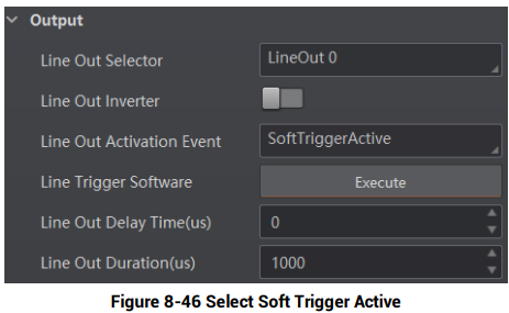
Figure 8-46 Select Soft Trigger Active
Figure description (text version): Output group: Line Out Selector LineOut 0, Line Out Inverter off, Line Out Activation Event SoftTriggerActive, Line Trigger Software (Execute button), Line Out Delay Time (us) 0, Line Out Duration (us) 1000.
Select Hard Trigger Active
If you select Hard Trigger Active as Line Out Activation Event, you can set its output delay time, duration, trigger source, and trigger activation.
Line Out Delay Time
It sets the delay time for outputting the output signal.
Line Out Duration
It sets the time duration of the output signal.
Hardware Trigger Source
It sets the hardware trigger source, including LineIn 0, LineIn 1, and LineIn 2.
Hardware Trigger Activation
It sets the trigger activation of input signal, including Rising Edge and Falling Edge.
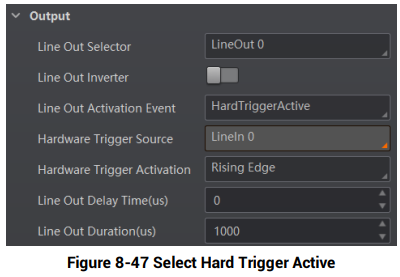
Figure 8-47 Select Hard Trigger Active
Figure description (text version): Output group: Line Out Selector LineOut 0, Line Out Inverter off, Line Out Activation Event HardTriggerActive, Hardware Trigger Source LineIn 0, Hardware Trigger Activation Rising Edge, Line Out Delay Time (us) 0, Line Out Duration (us) 1000.
Select Counter Active
If you select Counter Active as Line Out Activation Event, you can set its output delay time and duration.
Line Out Delay Time
It sets the delay time for outputting the output signal.
Line Out Duration
It sets the time duration of the output signal.
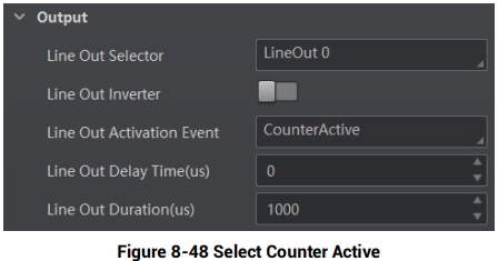
Figure 8-48 Select Counter Active
Figure description (text version): Output group: Line Out Selector LineOut 0, Line Out Inverter off, Line Out Activation Event CounterActive, Line Out Delay Time (us) 0, Line Out Duration (us) 1000.
Select Timer Active
If you select Timer Active as Line Out Activation Event, you can set its output duration and period.
Line Out Duration
It sets the time duration of the output signal.
Line Out Period
It sets the time period of the output signal.
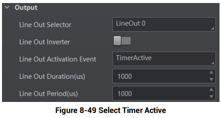
Figure 8-49 Select Timer Active
Figure description (text version): Output group: Line Out Selector LineOut 0, Line Out Inverter off, Line Out Activation Event TimerActive, Line Out Duration (us) 1000, Line Out Period (us) 1000.
Select No Code Read
If you select No Code Read as Line Out Activation Event, you can set its output delay time and duration.
Line Out Delay Time
It sets the delay time for outputting the output signal.
Line Out Duration
It sets the time duration of the output signal.
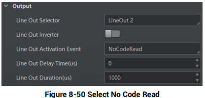
Figure 8-50 Select No Code Read
Figure description (text version): Output group: Line Out Selector LineOut 2, Line Out Inverter off, Line Out Activation Event NoCodeRead, Line Out Delay Time (us) 0, Line Out Duration (us) 1000.
Select Read Success
If you select Read Success as Line Out Activation Event, you can set its output delay time and duration.
Line Out Delay Time
It sets the delay time for outputting the output signal.
Line Out Duration
It sets the time duration of the output signal.
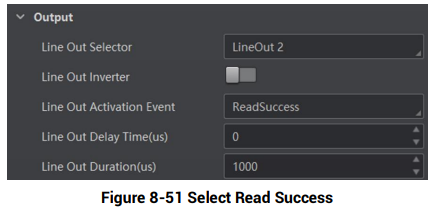
Figure 8-51 Select Read Success
Figure description (text version): Output group: Line Out Selector LineOut 2, Line Out Inverter off, Line Out Activation Event ReadSuccess, Line Out Delay Time (us) 0, Line Out Duration (us) 1000.
Select Light Strobe Long
If you select Light Strobe Long as Line Out Activation Event, you do not need to set any parameters.
Select Compare Success
If you select Compare Success as Line Out Activation Event, you can set its output delay time and duration.
Line Out Delay Time
It sets the delay time for outputting the output signal.
Line Out Duration
It sets the time duration of the output signal.
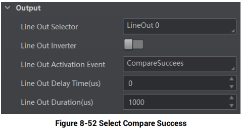
Figure 8-52 Select Compare Success
Figure description (text version): Output group: Line Out Selector LineOut 0, Line Out Inverter off, Line Out Activation Event CompareSuccess (shown in the software as "CompareSuccees"), Line Out Delay Time (us) 0, Line Out Duration (us) 1000.
Select Compare Fail
If you select Compare Fail as Line Out Activation Event, you can set its output delay time and duration.
Line Out Delay Time
It sets the delay time for outputting the output signal.
Line Out Duration
It sets the time duration of the output signal.
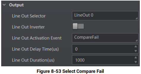
Figure 8-53 Select Compare Fail
Figure description (text version): Output group: Line Out Selector LineOut 0, Line Out Inverter off, Line Out Activation Event CompareFail, Line Out Delay Time (us) 0, Line Out Duration (us) 1000.
8.5 Indicator Customization
The device has 2 user-defined indicators, U1 and U2. They are used to indicate whether some functions of the device are normal or not after you selecting specific events.
Go to I/O Control Settings → LED, and set corresponding events according to actual demands. When the event you select occurs, indicators will flash once.
Table 8-3 Indicator Description
| No. | Parameters | Description |
|---|---|---|
| 1 | Off | No events. |
| 2 | Read Success | The indicators flash once when the device reads codes. |
| 3 | Who Am I | After selecting Who Am I, you can click Execute to let the indicators flash and know which device you are operating. |
| 4 | System Running | The indicators flash once when the device system operates. |
| 5 | Be Triggered | The indicators flash once when the device receives trigger signals. |
| 6 | LineOut 0 | The indicators flash once when LineOut 0 outputs signals. |
| 7 | LineOut 1 | The indicators flash once when LineOut 1 outputs signals. |
| 8 | LineOut 2 | The indicators flash once when LineOut 2 outputs signals. |
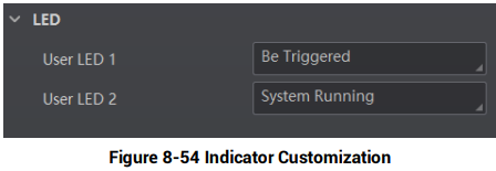
Figure 8-54 Indicator Customization
Figure description (text version): LED group: User LED 1 set to Be Triggered, User LED 2 set to System Running.
Słowa kluczowe
Hikrobot ID5000, trigger mode, software trigger, hardware trigger, counter trigger, TCP trigger, UDP trigger, serial trigger, self trigger, stop trigger, Line Out Selector, line inverter, event source, Read Success, No Code Read, indicator customization, User LED
No comments to display
No comments to display