
8. Device Settings – Part 5 (Communication, User Set, Statistics, Events)
Streszczenie: Ustawienia ID5000 cz. 5: protokoły komunikacyjne (Smart SDK, TCP Client/Server, Serial, FTP, Profinet, MELSEC, Ethernet/IP, ModBus, Fins, SLMP), zestawy ustawień użytkownika, statystyki odczytu i raport zdarzeń diagnostycznych.
EN: ID5000 settings part 5: communication protocols (Smart SDK, TCP Client/Server, Serial, FTP, Profinet, MELSEC, Ethernet/IP, ModBus, Fins, SLMP), user sets, reading statistics and diagnostic event report.
Dotyczy: przemysłowy czytnik kodów Hikrobot serii ID5000 (złącze M12 12-pin, Gigabit Ethernet, RS-232; obsługa przez klienta IDMVS)
Źródło: dokumentacja producenta (Hikrobot ID5000 Series Industrial Code Reader User Manual, V2.5.0); tabele i uwagi przepisane z obrazów na tekst; opisy rysunków – opracowanie Multiprojekt
Rozdział 8 „Device Settings” – części: Part 1 – Image Quality | Part 2 – Code Algorithm | Part 3 – Signal Input, Output and Indicator | Part 4 – Code Reading Result and Contrast Control | Part 5 – Communication, User Set, Statistics, Events
← poprzednia część
8.8 Communication Settings
The communication protocol is used to transmit and output code reading result and image. The communication protocol is related to the device modes. With various device modes, the device supports different communication protocols and corresponding parameters. When the device mode is Test or Raw, the device only supports Smart SDK protocol and no parameter settings are required. While in Normal mode, the device supports Smart SDK, TCP Client, TCP Server, Serial, FTP, Profinet, Melsec, Ethernet/IP, ModBus, Fins and SLMP communication protocols, and you need to set corresponding parameters.
Note: The specific communication parameters may differ by device models and firmware.
8.8.1 Smart SDK
If Smart SDK is selected as the Communication Protocols, you can enable SmartSdk Protocol to let the device output data via Smart SDK.
Encode JPG Flag
If enabled, the device will compress the image data.
Quality of JPG
You can enter a number (range: 50 to 99) to determine the compression quality.
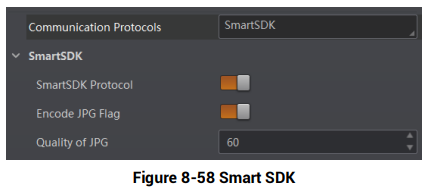
Figure 8-58 Smart SDK
Figure description (text version): Communication Protocols SmartSDK; SmartSDK group: SmartSDK Protocol on, Encode JPG Flag on, Quality of JPG 60.
8.8.2 TCP Client
The TCP includes TCP Server and TCP Client. If TCP Client is selected as the Communication Protocols, you can enable TCP Protocol, and enter TCP Dst Addr and TCP Dst Port.
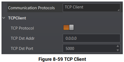
Figure 8-59 TCP Client
Figure description (text version): Communication Protocols TCP Client; TCPClient group: TCP Protocol on, TCP Dst Addr 0.0.0.0, TCP Dst Port 5000.
8.8.3 TCP Server
The TCP includes TCP Server and TCP Client. If TCP Server is selected as the Communication Protocols, you can enable TCP Server Enable, and enter TCP Server Port.
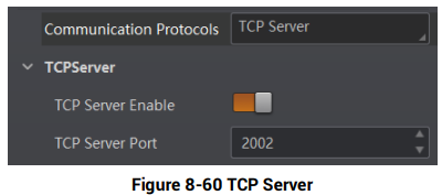
Figure 8-60 TCP Server
Figure description (text version): Communication Protocols TCP Server; TCPServer group: TCP Server Enable on, TCP Server Port 2002.
8.8.4 Serial
If Serial is selected as the Communication Protocols, you can enable Serial Protocol, enter Serial Baud Rate, Serial Data Bits, Serial Parity, and Serial Stop Bits.
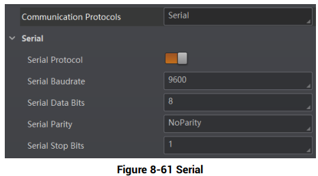
Figure 8-61 Serial
Figure description (text version): Communication Protocols Serial; Serial group: Serial Protocol on, Serial Baudrate 9600, Serial Data Bits 8, Serial Parity NoParity, Serial Stop Bits 1.
8.8.5 FTP
If FTP is selected as the Communication Protocols, you can enable FTP Protocol, enter FTP Host Addr, FTP Host Port, FTP User Name, and FTP User PWD.
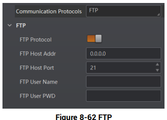
Figure 8-62 FTP
Figure description (text version): Communication Protocols FTP; FTP group: FTP Protocol on, FTP Host Addr 0.0.0.0, FTP Host Port 21, FTP User Name and FTP User PWD (empty).
8.8.6 Profinet
If Profinet is selected as the Communication Protocols, you can enable Profinet Enable and set Profinet Device Name according to actual demands.
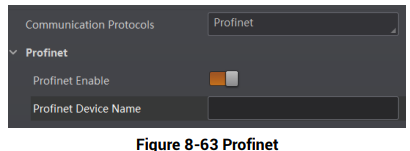
Figure 8-63 Profinet
Figure description (text version): Communication Protocols Profinet; Profinet group: Profinet Enable on, Profinet Device Name (empty).
8.8.7 MELSEC
If MELSEC is selected as the Communication Protocols, you can enable MELSEC Protocol Enable and set related parameters according to actual demands.
MELSEC Destination Address
It sets the IP address of the target PLC.
MELSEC Destination Port
It sets the port number of the target PLC.
MELSEC Data Base Address
It sets the first address of the data area.
MELSEC State Base Address
It sets the first address of the status area.
MELSEC Network Number
It sets the network No.
MELSEC PLC Number
It sets the PLC No.
MELSEC Module I/O Number
It sets the target module’s I/O number.
MELSEC Module Station Number
It displays the module station number.
MELSEC Timeout
It sets the waiting time before the returning of PLC’s response.
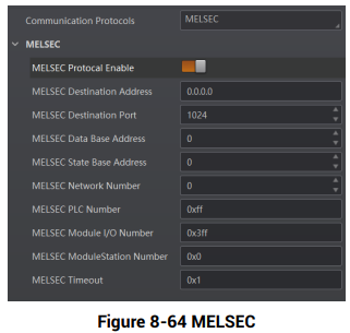
Figure 8-64 MELSEC
Figure description (text version): Communication Protocols MELSEC; MELSEC group: MELSEC Protocol Enable on, Destination Address 0.0.0.0, Destination Port 1024, Data Base Address 0, State Base Address 0, Network Number 0, PLC Number 0xff, Module I/O Number 0x3ff, Module Station Number 0x0, Timeout 0x1.
8.8.8 Ethernet/IP
If Ethernet/IP is selected as the Communication Protocols, you can enable Ethernet/IP Enable, and the device will output data via Ethernet/IP.
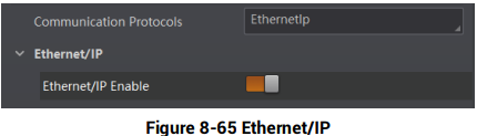
Figure 8-65 Ethernet/IP
Figure description (text version): Communication Protocols EthernetIp; Ethernet/IP group: Ethernet/IP Enable on.
8.8.9 ModBus
If ModBus is selected as the Communication Protocols, you can enable ModBus Enable and set related parameters according to actual demands.
ModBus Mode
It includes server and client, and is server by default.
Note: If client is selected as ModBus Mode, you need to set ModBus Server IP, ModBus Server Port and ModBus Scan Rate (ms).
ModBus Control Address Space
It is holding_register by default.
ModBus Control Address Offset
It refers to the address offset, and is 0 by default.
ModBus Control Data Number
It is 2 by default.
ModBus State Address Space
It is input_register by default.
ModBus State Address Offset
It is 0 by default.
ModBus State Data Number
It is 2 by default.
ModBus Result Address Space
It is input_register by default.
ModBus Result Address Offset
It is 4 by default.
ModBus String Byte Swap
If it is enabled, string byte is saved by big-endian. If it is not enabled, string byte is saved by little-endian.
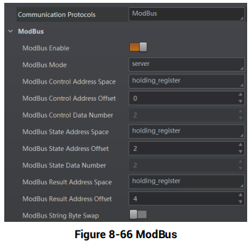
Figure 8-66 ModBus
Figure description (text version): Communication Protocols ModBus; ModBus group: ModBus Enable on, ModBus Mode server, Control Address Space holding_register, Control Address Offset 0, Control Data Number 2, State Address Space holding_register, State Address Offset 2, State Data Number 2, Result Address Space holding_register, Result Address Offset 4, String Byte Swap off.
8.8.10 Fins
If Fins is selected as the Communication Protocols, you can enable Fins Enable and set related parameters according to actual demands.
Fins Communication Mode
It includes UDP or TCP.
Fins Local Port
It is 9600 by default.
Fins Dst IP
It sets the IP address of the target device.
Fins Dst Port
It sets the port of the target device.
Fins Data Format
It includes 16-bit or 32-bit.
Fins Scan Rate (ms)
It sets the interval that the device reads the server’s control register, and the unit is ms.
Fins Control Area
It is saved in DM area by default.
Fins Control Addr
You can set it according to actual demands. Make sure that each area cannot be overlapped and covered.
Fins State Area
It is saved in DM area by default.
Fins State Addr
You can set it according to actual demands. Make sure that each area cannot be overlapped and covered.
Fins Result Area
It is saved in DM area by default.
Fins Result Addr
You can set it according to actual demands. Make sure that each area cannot be overlapped and covered.
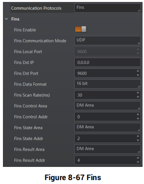
Figure 8-67 Fins
Figure description (text version): Communication Protocols Fins; Fins group: Fins Enable on, Communication Mode UDP, Local Port 9600, Dst IP 0.0.0.0, Dst Port 9600, Data Format 16 bit, Scan Rate (ms) 30, Control Area DM Area, Control Addr 0, State Area DM Area, State Addr 2, Result Area DM Area, Result Addr 4.
8.8.11 SLMP
If SLMP is selected as the Communication Protocols, you can enable SLMP Enable and set related parameters according to actual demands.
SLMP Dst Addr
It sets the IP address of the target PLC.
SLMP Dst Port
It sets the port number of the target PLC.
SLMP Data Base Addr
It sets the first address of the data area.
SLMP State Base Addr
It sets the first address of the status area.
SLMP Network Num
It sets the network No.
SLMP PLC Num
It sets the PLC No.
SLMP Module I/O Num
It sets the target module’s I/O number.
SLMP Module Station Num
It displays the module station number.
SLMP Timeout
It sets the waiting time before the returning of PLC’s response.
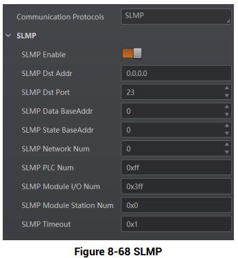
Figure 8-68 SLMP
Figure description (text version): Communication Protocols SLMP; SLMP group: SLMP Enable on, Dst Addr 0.0.0.0, Dst Port 23, Data BaseAddr 0, State BaseAddr 0, Network Num 0, PLC Num 0xff, Module I/O Num 0x3ff, Module Station Num 0x0, Timeout 0x1.
8.9 User Set Customization
The Configuration Management module allows you to set and manage the user set. A user set is a group of parameter values with all the settings needed to control the device, and you can save, load and switch different user sets.
Save Settings
If you have set the device parameters as desired, you can save them into the user set. Go to Config Management → Save Settings, and click UserSet1, UserSet2, or UserSet3 to save the current device settings.
Load Settings
You can load the user set to restore the device to the saved group of parameter values again if required. Go to Config Management → Load Settings, and click Default, UserSet1, UserSet2, or UserSet3 to load settings.
Note: Default refers to restoring the device parameter settings to the factory ones.
Start Settings
The selected user set will be automatically loaded after the device being powered on. For example, if you select Default, the device parameter settings will be restored to the factory settings.
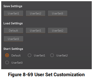
Figure 8-69 User Set Customization
Figure description (text version): Configuration panel: Save Settings buttons UserSet1–UserSet3; Load Settings buttons Default and UserSet1–UserSet3; Start Settings radio buttons Default (selected), UserSet1, UserSet2, UserSet3.
8.10 Statistics Information
The statistics information in the feature tree helps you to count data related with code reading.
Note: You need to set device mode as Normal before using this function.
Go to feature tree, find Statistics Info., and select Statistics Mode according to actual demands. Two statistics modes are available:
All Frames means that the client software will display all data since the device is powered on. Latest Frames means that the client software will display data of the last 10 frames.
Refer to the table below for specific parameters.
Table 8-4 Parameter Description
| Parameter Name | Description |
|---|---|
| Total Frame Number | The total frame quantity. |
| Read Frame Number | The quantity of frames in which codes have been read. |
| Noread Frame Number | The quantity of frames in which codes have not been read. |
| Read Rate | It refers to the code reading ratio. |
| Algo Time Ave. | The average time of algorithm, and the unit is ms. |
| Algo Time Max. | The max. time of algorithm, and the unit is ms. |
| Algo Time Min. | The min. time of algorithm, and the unit is ms. |
| Read Time Ave. | The average time of code reading, and the unit is ms. |
| Read Time Max. | The max. time of code reading, and the unit is ms. |
| Read Time Min. | The min. time of code reading, and the unit is ms. |
| Reset Statistics | Click Execute to reset statistics information. |
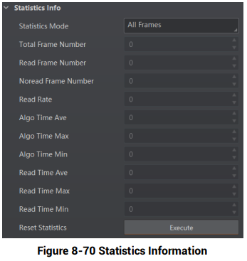
Figure 8-70 Statistics Information
Figure description (text version): Statistics Info group: Statistics Mode All Frames, followed by read-only counters (Total Frame Number, Read Frame Number, Noread Frame Number, Read Rate, Algo Time Ave/Max/Min, Read Time Ave/Max/Min, all 0) and the Reset Statistics Execute button.
8.11 Event Report
The diagnose event report function in the feature tree monitors memory and CPU usage rate, and let you know when there is a crash, higher CPU usage rate, insufficient memory, and other events.
Go to feature tree, find Diagnose Event Report, and you can view related information as shown below. You can click Execute in Reset Event to clear all information.
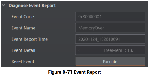
Figure 8-71 Event Report
Figure description (text version): Diagnose Event Report group: Event Code 0x30000004, Event Name MemoryOver, Event Report Time 20201124_152610691, Event Detail (JSON text, e.g. "FreeMem": 18), Reset Event (Execute).
Słowa kluczowe
Hikrobot ID5000, communication protocols, Smart SDK, TCP Client, TCP Server, Serial, FTP, Profinet, MELSEC, Ethernet/IP, ModBus, Fins, SLMP, PLC, user set, UserSet1, statistics, read rate, event report
No comments to display
No comments to display