
9. Device Operation
Streszczenie: Podstawowe operacje czytnika ID5000 w IDMVS: podgląd na żywo, akwizycja, linia krzyżowa, nagrywanie, podział okna, statystyki, dziennik urządzenia, synchronizacja czasu NTP i automatyczna praca po włączeniu.
EN: ID5000 basic operations in IDMVS: live view, acquisition, cross line, recording, window split, reports, device log, NTP time and device auto work.
Dotyczy: przemysłowy czytnik kodów Hikrobot serii ID5000 (złącze M12 12-pin, Gigabit Ethernet, RS-232; obsługa przez klienta IDMVS)
Źródło: dokumentacja producenta (Hikrobot ID5000 Series Industrial Code Reader User Manual, V2.5.0); opisy rysunków – opracowanie Multiprojekt
The device operation section introduces some basic device operations about how to start live view, acquisition and recording, add cross line in the image, split window, view reports, etc.
Note: Connecting the device to the client software is required before device operation.
9.1 Live View
You can view the real-time image in the live view window.
Click  in live view window to start live view, or click
 to stop.
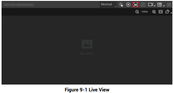
Figure 9-1 Live View
Figure description (text version): Live view window (mode Normal) with the live view button highlighted in red in the toolbar; no video is displayed yet.
9.2 Enable Acquisition
Enabling acquisition allows the device to acquire the real-time stream.
Click  in live view window to start acquisition, or click
 to stop. You can also right click the device on the device list, and click Stop Acquisition to stop acquiring streams.
Note: Acquisition is still going on if you only stop live view.
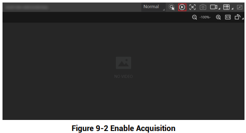
Figure 9-2 Enable Acquisition
Figure description (text version): Live view window (mode Normal) with the start acquisition button highlighted in red in the toolbar.
9.3 Add Cross Line
During live view, you can add a cross line on the live view image to adjust the position of the object in the view.
Click  in live view window to add cross line, and click
 (beside
 ) to open the editing window to set cross line parameters.
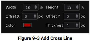
Figure 9-3 Add Cross Line
Figure description (text version): Cross line editing window: Width 18 %, Height 15 %, Offset X 0 px, Offset Y 0 px, Color (red), Thickness 1 px.
9.4 Start Recording
During live view, you can record video files and capture images continuously.
Note: Enabling acquisition is required before recording.
Click  in live view window to start recording, and click the icon again to stop. You can also click
 (beside
 ), and then click
 to capture images of the live view continuously.
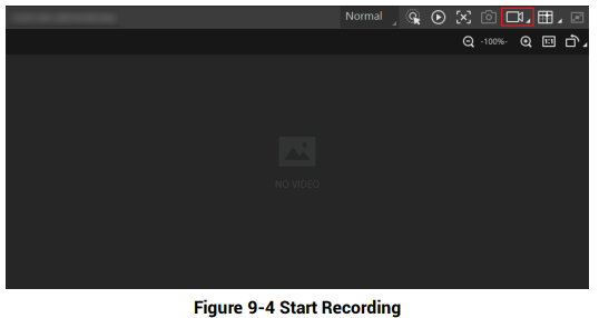
Figure 9-4 Start Recording
Figure description (text version): Live view window (mode Normal) with the record button highlighted in red in the toolbar.
9.5 Split Window
The client software supports window division function that allows you to split the window into multiple-window mode to view the live view of multiple devices at the same time.
Click  in control toolbar to select window division mode. You can click Custom to customize window division as you desired.
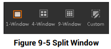
Figure 9-5 Split Window
Figure description (text version): Window division menu with options 1-Window (selected), 4-Window, 9-Window and Custom.
9.6 View Reports
During acquisition or live view, you can view the reading status of the device.
Click  in control toolbar to open the statistics window to view the detailed information. Read Code Images refers to the number of the images on which the barcodes are read by the device. Unread Code Images refers to the number of the images on which the barcodes are not read by the device. Read Rate refers to the code reading rate.
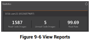
Figure 9-6 View Reports
Figure description (text version): Statistics window for one device: Read Code Images 1587, Unread Code Images 5, Read Rate 99.69.
9.7 View Log
You can view the device logs and export them to the local PC.
Click  in control toolbar to open the device log window, and you can view different types of logs, including device errors, warning, and informational log, etc.
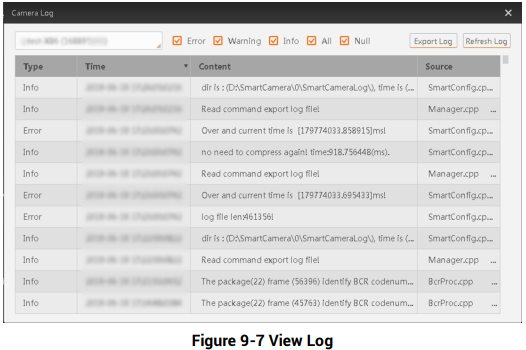
Figure 9-7 View Log
Figure description (text version): Camera Log window: device selector, filter check boxes Error, Warning, Info, All, Null, buttons Export Log and Refresh Log, and a table with columns Type (Info/Error), Time, Content and Source (e.g. SmartConfig.cpp, Manager.cpp, BcrProc.cpp).
9.8 Set Time
After enabling NTP time synchronization, the device will synchronize time according to the configured interval.
Steps
- Go to Config Management, and find Timing.
- Click Setting and enable NTP Enable.
- Set parameters according to actual demands
Note: Configure NTP server settings before using NTP time synchronization function.
- Click OK after settings.
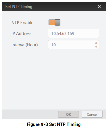
Figure 9-8 Set NTP Timing
Figure description (text version): Set NTP Timing dialog: NTP Enable switched on, IP Address 10.64.63.169, Interval (Hour) 10, OK and Cancel buttons.
9.9 Enable Device Auto Work
This function allows the device to automatically enter the operating status after being powered on.
You can go to Config Management → Device Auto Work Enable, and enable Device Auto Work Enable.
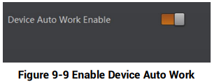
Figure 9-9 Enable Device Auto Work
Figure description (text version): Config Management panel with the Device Auto Work Enable switch turned on.
Słowa kluczowe
Hikrobot ID5000, live view, acquisition, cross line, recording, split window, statistics, read rate, device log, NTP, time synchronization, device auto work
No comments to display
No comments to display