
11. Control Loops – Current Loop
Streszczenie: Pętla prądowa: kroki strojenia każdej pętli, podstawowe ustawienia i ręczne strojenie pętli prądowej, automatyczne strojenie (Auto Tune) oraz uwagi o trybie prądowym – schemat, wejścia, offset, limity, wzmocnienia Cp/Ci i wyjście.
EN: Control loops, part 1: current loop setup, manual and auto tuning, and current loop notes.
Dotyczy: program CME 2 do konfiguracji i strojenia serwonapędów oraz napędów krokowych Copley Controls (m.in. Xenus, Accelnet, Stepnet, Accelus, Junus)
Źródło: dokumentacja producenta (Copley Controls CME 2 User Guide); tabele przepisane z obrazów na tekst – opracowanie Multiprojekt
Rozdział 11 „Control Loops” podzielono na 3 strony: Current Loop · Velocity Loop · Position Loop and Auto Tune.
This chapter shows how to program and tune the control loops. Perform the basic steps outlined below. Details follow in the chapter.
For each control loop
1 or
 or
 Click the appropriate button to open the loop control screen.
2.  Change/verify settings as needed.
3.  Click Close to close screen and save changes to amplifier RAM.
4.  Click to open the Scope tool.
5.  Run a function or profile and adjust settings to tune the loop.
For an overview of control loop theory, see Servo Operating Modes and Control Loops.
11.1 Current Loop Setup and Tuning
Initial current loop proportional gain (Cp) and current loop integral gain (Ci) values can be calculated with The Calculate Function.
Enter basic Current Loop settings
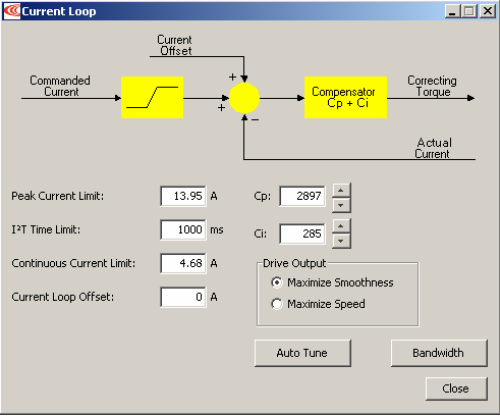
1.  Click I Loop to open the Current Loop screen:
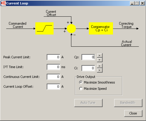
2. Change/verify Current Loop parameters as needed
Current Loop – parameters
| Parameter | Description |
|---|---|
| Peak Current Limit | Used to limit the peak phase current to the motor. Max value depends upon the amplifier model; Min value > continuous limit. |
| I²T Time Limit | Sets I²T Time Limit in mS. See I²T Time Limit Algorithm. |
| Continuous Current Limit | Used to limit the Phase Current. Max Value is < Peak Current and depends upon the amplifier model. Min value: 0. |
| Current Loop Offset | Sets current loop offset. Leave it set to zero until after tuning. For more information, see Offset. |
| Cp | Current loop proportional gain. Range 0 – 32,767. |
| Ci | Current loop integral gain. Range 0 – 32,767. |
| Drive Output | Maximize Smoothness: Amplifier uses circular vector limiting to produce smooth operation even into the voltage limits. Maximize Speed: Allows for slightly more of the bus voltage to be used when in the voltage limit. This may produce a small disturbance at top speed. |
| Auto Tune | See Current Loop Auto Tune. |
| Bandwidth | Measure bandwidth using the Cp and Ci values now in the amplifier. |
3. Click Close to close screen and save changes to amplifier RAM
Manually tune the Current Loop
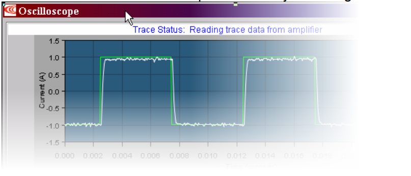
METHOD: Apply square-wave excitation to the current loop and adjust current loop proportional gain (Cp) and current loop integral gain (Ci) to obtain a desired waveform.
For instance:
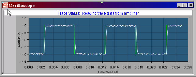
NOTES:
1) During tuning, observe any warnings that appear to the left of the trace.
2) Some users prefer the Auto Tune feature. See Current Loop Auto Tune
1.  Click the Scope Tool.
2.  Choose Current from theFunction Generator Apply To: list.
3.  On the Settings tab, make sure Auto Setup is selected. Auto Setup automatically sets the following parameters:
Scope settings for current loop tuning
| Parameter | Description |
|---|---|
| Function Generator Tab | |
| Function | Square Wave. |
| Amplitude | 10% of continuous current value. |
| Frequency | 100 Hz. |
| Settings Tab | |
| Channel 1 | Commanded current (green). |
| Channel 2 | Actual current (white). |
5.  Click Start.
6. 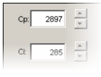 On the Gains tab, adjust current loop proportional gain (Cp):
Set current loop integral gain (Ci) to zero.
Raise or lower Cp to obtain desired step response. (Typically, little or no overshoot with a 100 Hz, low-current square wave.) If the Cp value is too large, ringing may occur. If the Cp value is too low, bandwidth decreases.
7. Adjust current loop integral gain (Ci) until desired settling time is obtained.
8.  Press Stop to stop the function generator.
9 On the Main screen, click Save to Flash to avoid losing the changes.
11.2 Current Loop Auto Tune
Tune the Current Loop with Auto Tune
METHOD: The current loop Auto Tune algorithm applies a square-wave command to the current loop and adjusts current loop proportional gain (Cp) and current loop integral gain (Ci) until a desirable waveform is obtained. Initial current loop proportional gain (Cp) and current loop integral gain (Ci) values can be calculated with The Calculate Function.
1.  Click I Loop to open the Current Loop screen:
2. Verify that the amplifier is hardware enabled.
3.  Click Auto Tune to open screen and start the Current Loop Auto Tune.
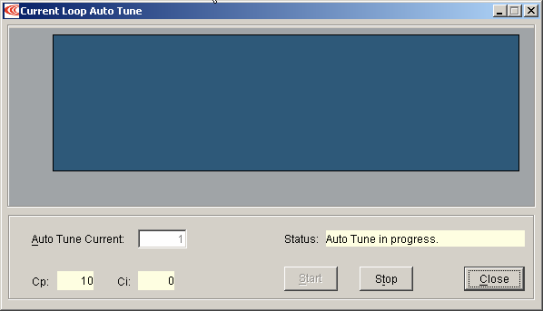
4. To Change the Auto Tune Current, Press Stop, enter the new current in the Auto Tune Current field, and then press Start.
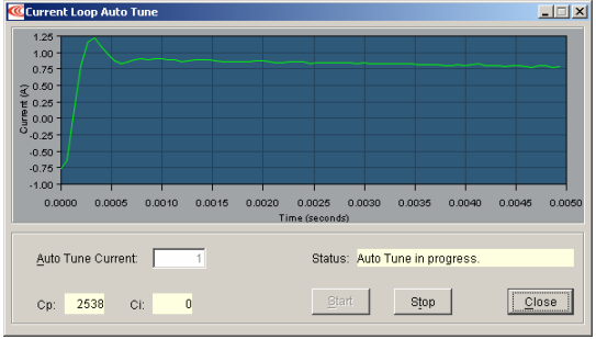
5. Observe the Auto Tune process and results. A typical example:
Sets Cp and Ci to zero and then adjusts Cp and Ci for optimal values.
Uses a frequency sweep to determine the small signal, current loop bandwidth.
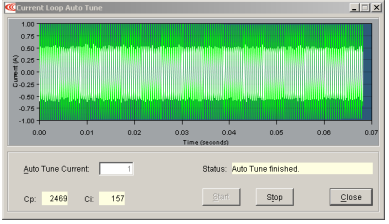
Displays the results: a set of Cp and Ci alternatives, and the bandwidth measured using the high Cp and Ci values.
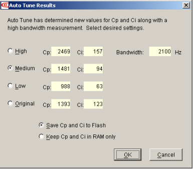
6. Choose an action based on Auto Tune results.
Choose which set of values to save: High, Medium, Low, or Original. The Medium values, selected by default, are appropriate for most applications.
Optionally choose how to save: Save Cp and Ci to Flash or Keep Cp and Ci in amplifier RAM only.
7. Click OK to save the values as chosen, and close the Auto Tune Results window.
11.3 Notes on the Current Mode and Current Loop
11.3.1 Current Loop Diagram
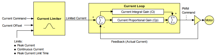
As shown below, the “front end” of the current loop is a limiting stage. The limiting stage accepts a current command, applies limits, and passes a limited current command to the summing junction. The summing junction takes the commanded current, subtracts the actual current (represented by the feedback signal), and produces an error signal. This error signal is then processed using the integral and proportional gains to produce a command. This command is then applied to the amplifier’s power stage.
11.3.2 Current Loop Inputs
- The amplifier’s analog or PWM inputs.
- A CANopen network via the amplifier’s CAN interface.
- A Copley Virtual Motion (CVM) control program.
- The amplifier’s internal function generator.
In velocity or position modes, the current command is generated by the velocity loop
11.3.3 Offset
The current loop offset is intended for use in applications where there is a constant force applied to, or required of, the servomotor and the system must control this force. Typical applications would be a vertical axis holding against gravity, or web tensioning. This offset value is summed with the current command before the limiting stage.
11.3.4 Limits
The current command is limited based on the following parameters:
Current limiters
| Limiter | Description |
|---|---|
| Peak Current Limit | Maximum current that can be generated by the amplifier for a short duration of time. This value cannot exceed the peak current rating of the amplifier. |
| Continuous Current Limit | Maximum current that can be constantly generated by the amplifier. |
| I²T Time Limit | Maximum amount of time that the peak current can be applied to the motor before it must be reduced to the continuous limit or generate a fault. For more details, see I²T Time Limit Algorithm. Note: Although the current limits set by the user may exceed the amplifier’s internal limits, the amplifier operates using both sets of limits in parallel, and therefore will not exceed its own internal limits regardless of the values programmed. |
| Ramp | Rate of change in current command. Used to limit jog moves initiated from the Control Panel Jog function in current mode, and in advanced Indexer Program functions. |
11.3.5 Current Loop Gains
The current loop uses these gains:
Current loop gains
| Gain | Description |
|---|---|
| Cp - Current loop proportional | The current error (the difference between the actual and the limited commanded current) is multiplied by this value. The primary effect of this gain is to increase bandwidth (or decrease the step-response time) as the gain is increased. |
| Ci - Current loop integral | The integral of the current error is multiplied by this value. Integral gain reduces the current error to zero over time. It controls the DC accuracy of the loop, or the flatness of the top of a square wave signal. The error integral is the accumulated sum of the current error value over time. |
11.3.6 Current Loop Output
The output of the current loop is a command that sets the duty cycle of the PWM output stage of the amplifier.
Słowa kluczowe
pętla prądowa, strojenie, Auto Tune, Cp, Ci, limit prądu szczytowego, prąd ciągły, I2T, offset, Scope
No comments to display
No comments to display