
5. Motor/Feedback
Streszczenie: Ekran Motor/Feedback: parametry silników obrotowych i liniowych, parametry enkodera i resolwera (także podwójne sprzężenie), wczytywanie danych silnika z pliku, parametry i przebieg czasowy hamulca/zatrzymania (Brake/Stop) oraz funkcja Calculate wyznaczająca początkowe wzmocnienia i limity.
EN: Motor/Feedback screen: rotary and linear motor parameters, feedback settings, brake/stop timing and the Calculate function.
Dotyczy: program CME 2 do konfiguracji i strojenia serwonapędów oraz napędów krokowych Copley Controls (m.in. Xenus, Accelnet, Stepnet, Accelus, Junus)
Źródło: dokumentacja producenta (Copley Controls CME 2 User Guide); tabele przepisane z obrazów na tekst, opisy diagramów – opracowanie Multiprojekt
This chapter describes motor, feedback, and brake parameters, and the Calculate function. Access these features as described below. Details follow in the chapter.
1.  Click Motor/Feedback to open the Motor/Feedback screen.
2.  Load Motor/Feedback/Brake Settings from a File
OR
Step 2: Enter settings manually
 Click the Motor tab to view or change Rotary Motor Setup Parameters or Linear Motor Setup Parameters
 Click the Feedback tab to view or change Feedback Parameters, Rotary or Feedback Parameters, Linear . Read the Feedback Notes for important related information.
 Click the Brake/Stop tab to view or change Brake/Stop Parameters. Read the Brake/Stop Notes for important related information.
 Use The Calculate Function to calculate initial gains and limits.
 On the Main screen, click Save to Flash to avoid losing the changes.
5.1 Motor/Feedback Screen Overview
A typical Motor/Feedback screen is shown below. Parameters vary with amplifier model.
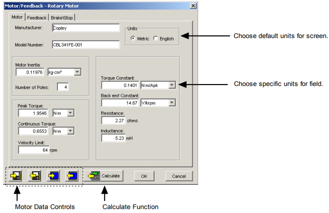
The Calculate function is described in The Calculate Function Data on the Motor/Feedback screen can be saved to and restored from disk files using the controls described below.
Motor/Feedback screen tools
| Name | Description |
|---|---|
| Save motor data to disk | Saves motor/feedback/brake settings from PC to a disk file with .ccm name extension. |
| Restore motor data from disk | Restores contents of a .ccm file from disk to PC. |
| Save motor data to flash | Saves motor/feedback/brake settings from PC to amplifier permanent flash memory. |
| Restore motor data from flash | Restores motor/feedback/brake settings from flash memory to the PC. |
For more information see Data, Firmware, and Logs
5.2 Load Motor/Feedback/Brake Settings from a File
1. If needed, download the motor data file from the Copley Controls website: In an internet browser, navigate to http://www.copleycontrols.com/Motion/Downloads/motorData.html Click on the appropriate motor name.
When prompted, save the file to the MotorData folder in the CME 2 installation folder.
(The default installation folder is C:\Program Files\Copley Motion\CME 2\MotorData.)
Extract the contents of the zip file to the same location.
The folder should now contain the new motor data file (with a .ccm filename extension).
If desired, delete the .zip file to save disk space.
2. Load the motor data into the amplifier:
 Click Motor/Feedback to open the Motor/Feedback screen.
On the Motor/Feedback screen, click Restore Motor Data from Disk. When prompted, navigate to the folder containing the file, then click on the file name, and then click Open.
 Calculate initial gains and limits with The Calculate Function
 On the Main screen, click Save to Flash to avoid losing the changes.
5.3 Rotary Motor Setup Parameters
View or change the settings described below. Options vary with amplifier model. Metric units are shown here.
Motor/Feedback – Motor tab (rotary motor)
| Setting | Description |
|---|---|
| Manufacturer | Motor manufacturer’s name. Saved for reference in the motor data file. |
| Model Number | Motor model number. Saved for reference in the motor data file. |
| Units | Selects whether the parameters entered in this screen are in Metric or English units. |
| Motor Inertia | The rotor inertia of the motor. Used for calculating initial velocity loop tuning values. Range: 0.00001 to 4,294 kg cm². Default: 0.00001 kg-cm². |
| Number of Poles | (Brushless only.) The number of magnetic poles in the motor. Required for correct commutation of the motor. If the number of poles is not known, Verify the motor’s pole count. Range: 2 to 200. Default: 4. |
| Peak Torque | The peak torque that the motor can produce. Peak Torque divided by torque constant = motor’s peak current limit. Range: 0.001 to 2,100 Nm. Default: 0.0001 Nm. |
| Continuous Torque | The continuous torque that the motor can produce. Used with the torque constant to calculate continuous current. Range: 0.001 to 1,000 Nm. Default: 0.0001 Nm. |
| Velocity Limit | Maximum speed of the motor. Used to calculate the velocity and acceleration limits for the velocity loop. Range dependent on encoder resolution. |
| Torque Constant | Relates the motor’s input current to torque produced. Sometimes abbreviated as Kt. Range: 0.001 to 1,000 Nm/Apk. Default: 0.001 Nm/Apk. |
| Back emf Constant | Relates the motor’s input voltage to speed. Sometimes abbreviated as Ke. Used for calculating the maximum velocity for a given amplifier bus voltage. Range: 0.01 to 21,000,000 V/Krpm. Default: 0.01 V/Krpm. |
| Resistance | Motor resistance line-to-line. Used for calculating the initial current loop tuning values. Range: 0.01 to 327 Ω. Default: 0.01 Ω. |
| Inductance | Motor inductance line-to-line. Used for calculating the initial current loop tuning values. Range: see the hardware documentation. |
| Stepper Amplifiers Only | |
| Rated Torque | Motor’s rated operating torque. Min: .001. Max: 1000. |
| Rated Current | Motor’s rated continuous current. Min: 0.001. Max: 1000. |
| Basic Step Angle | Fundamental stepper motor step, in degrees. Min: 0.225. Max: 22.5. Default 1.8. |
| Microsteps/Rev | Number of microsteps per revolution of the motor. Min: 4. Max: 100,000,000. Default 4000. |
| Full Steps/Rev | This read-only value can be used after entering Basic Step Angle to cross-check against motor data sheet. |
5.4 Linear Motor Setup Parameters
View or change the settings described below. Options vary with amplifier model. Metric units are shown here.
Motor/Feedback – Motor tab (linear motor)
| Setting | Description |
|---|---|
| Manufacturer | Motor maker’s name. Saved in the motor data file. Choose from list or enter manually. |
| Model Number | Motor model number. Saved in the motor data file. Choose from list or enter manually. |
| Units | Selects whether the parameters entered in this screen are in Metric or English units. |
| Mass | The mass of the motor. Used for calculating initial velocity loop tuning values. Range: .0001 Kg to 100,000 Kg. Default: .0001 Kg. |
| Peak Force | The peak force that the motor can produce. Peak Force divided by Force Constant = motor’s peak current limit. Range: 0.00001 to 2,000 N. Default: 0.00001 N. |
| Continuous Force | The continuous force that the motor can produce. Used with the force constant to calculate continuous current. Range: 0.00001 to 1,000 N. Default: 0.00001 N. |
| Velocity Limit | Maximum speed of the motor. Used to calculate the velocity and acceleration limits for the velocity loop. Range dependent on encoder resolution. |
| Force Constant | Relates the motor’s input current to force produced. Sometimes abbreviated as Kf. Range: 0.00001 to 2,000 N/Amp. Default: 0.00001 N/Amp. |
| Back emf Constant | Relates the motor’s input voltage to speed. Sometimes abbreviated as Ke. Used for calculating maximum velocity for a given amplifier voltage. Range: 0.01 to 1,000 V/M/Sec. Default: 0.01 V/M/Sec. |
| Resistance | Motor resistance line to line. Used for calculating the initial current loop tuning values. Range: 0.01 to 327 Ω. Default: 0.01 Ω. |
| Inductance | Motor inductance line to line. Used for calculating the initial current loop tuning values. Range: see the hardware documentation. |
| Magnetic Pole Pair Length | The length of a pair of magnets which equals the distance moved in one electrical cycle of the motor. |
| Stepper Amplifiers Only | |
| Rated Force | Motor’s rated operating force. Min .001 N. Max 1000 N. |
| Rated Current | Motor’s rated continuous current. Min: 0.01 A. Max 1000 A. |
| Full Step | Fundamental stepper motor step distance. Min: 0.0001mm. Max: 5000 mm. |
| Microsteps/Full Step | Number of microsteps per full step. Min: 1. Max: 100,000,000. |
5.5 Feedback Parameters, Rotary
As appropriate for each encoder or resolver, enter the parameters described here. Options vary with amplifier model.
Feedback tab – feedback resolution by feedback type
| Feedback Type | Parameters/Actions |
|---|---|
| Incremental | In the Motor Encoder lines or Position Encoder lines field, enter the number of encoder lines (see encoder or motor data sheet). As indicated by the counts field, the number of encoder counts per revolution is equal to 4 x the number of lines (example: 1000 lines = 4000 counts). |
| Analog | In Fundamental Lines, enter the number of fundamental encoder lines (see encoder or motor data sheet). As indicated by the Fundamental Counts field, the number of fundamental encoder counts per revolution is equal to 4 x the number of Fundamental Lines. Optionally modify the encoder resolution by changing the Interpolation value. The interpolated resolution (Interpolated Counts Per Rev) is the product of Fundamental Counts value and the Interpolation value (example: 1000 lines = 4000 fundamental counts; interpolation 1 → 4000 interpolated counts per rev). |
| Resolver | Optionally modify the feedback resolution by changing the value in Counts Per Rev. Default: 16384. |
| Halls | With amplifier set to Use Halls for Velocity/Position, optionally increase the counts per rev ratio by incrementing the Halls Count Multiplier (example: multiplier 1 → 12 counts per rev; Default button restores the default). |
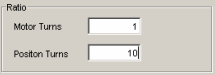
If two feedback devices are installed, verify that the values of Motor Turns to Position Turns correctly represent the ratio of motor encoder turns to position encoder turns. The details of the following screen may vary depending on the types of feedback devices present.
5.6 Feedback Parameters, Linear
As appropriate for each encoder installed, enter the parameters described below. Options vary with amplifier model
Feedback tab – linear motor feedback resolution by feedback type
| Feedback Type | Parameters/Actions |
|---|---|
| Incremental | Choose units (mm, um or nm) and then enter the Encoder Resolution (see encoder or motor data sheet). |
| Analog | Enter the Fundamental Pitch (distance between encoder lines; see encoder or motor data sheet). As indicated by the Fundamental Resolution field, Fundamental Pitch divided by four gives Fundamental Resolution. The interpolated resolution is the dividend of Fundamental Resolution value/Interpolation value. Optionally modify the Interpolated Resolution by changing the Interpolation value (example: pitch 4 um → fundamental resolution 1 um; interpolation 1 → interpolated resolution 1 um). |
| Low Frequency Analog | (Normally used with ServoTube) Pole Pitch is the distance between poles in a pole pair, as entered in the Magnetic Pole Pair Length field on the Motor tab. The interpolated resolution is the dividend of Pole Pitch/Counts per pole value, expressed in micrometers. Optionally modify the resolution by changing the Counts/Pole value. Click Restore Default to restore default Counts/Pole (example: pole pitch 51.2 mm, 4000 counts/pole → interpolated resolution 12.8 um). |
5.7 Feedback Notes
5.7.1 Encoder and Resolver Support
Some Copley Controls amplifiers are offered in multiple versions to support different types of encoder or resolver feedback. Some encoder versions support digital quadrature encoders, some support analog sin/cos encoders, and others support both. Encoder versions normally require Hall switches for the commutation of brushless motors. The resolver versions support standard, single speed, transmit-type resolvers.
5.7.2 Dual Feedback Amplifiers
Some Copley Controls amplifiers can receive position feedback from sensors on the motor, the load, or both, through the Primary Feedback channel, a Secondary Feedback channel (multi-mode port) or both. (Some amplifiers can also operate in certain modes without encoders or resolvers.)
When the amplifier is configured with a multi-mode port (see Feedback Options, p. 32) the multi-mode port can:
- Provide a buffered digital encoder output based on the digital encoder input.
- Provide an emulated digital encoder output based on the analog encoder or resolver input.
- Provide a second digital encoder input to be used in the dual encoder position mode. In this mode, an encoder attached to the load provides position loop feedback, and the motor encoder or resolver provides velocity loop feedback.
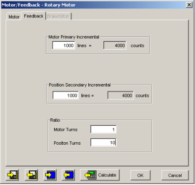
A dual-feedback setup is shown below. The amplifier receives feedback from an incremental motor encoder through the Primary feedback channel. Position (load) encoder feedback comes through the multi-mode port. The ratio of motor turns to position encoder turns is 1 to 10
5.8 Brake/Stop Parameters
Enter the following parameters as appropriate.
Brake/Stop parameters
| Parameter | Description |
|---|---|
| Brake/Stop Delay Time | Range of accepted values: 0 to 10,000 mSec. |
| Brake Activation Velocity | Range of accepted values: 0 to 183,105 rpm (mm/s for linear motor). |
| PWM Delay Brake/Stop Response Time | Range of accepted values: 0 to 10,000 mSec. |
5.9 Brake/Stop Notes
Many control systems employ a brake to hold the axis when the amplifier is disabled. On brake-equipped systems, disabling the amplifier by a hardware or software command starts the following sequence of events.
- The motor begins to decelerate (at Abort Deceleration rate in position mode or Fast Stop Ramp rate in velocity mode). At the same time, the Brake/Stop Delay Time count begins. This allows the amplifier to slow the motor before applying the brake.
- When the motor slows to Brake/Stop Activation Velocity OR the Brake/Stop Delay Time expires, the brake output activates and PWM Delay Brake/Stop Response Time count begins.
- When response time has passed, the amplifier’s output stages are disabled. This delay ensures the brake has time to lock in before disabling the power section.
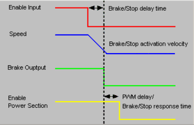
Diagram description (text version): Brake/Stop timing: when the Enable Input goes inactive, the drive decelerates the motor (Speed falls). When the speed reaches the Brake/Stop activation velocity, or after the Brake/Stop delay time has elapsed, the Brake Output is activated. The power section (Enable Power Section) stays on for the PWM delay / Brake/Stop response time so the brake can lock in, and only then is disabled.
This sequence is not available in the current mode of operation. Instead, in current mode, the amplifier output turns off and the brake output activates immediately when the disable command is received.
5.10 The Calculate Function
The Calculate function uses programmed motor and encoder values to calculate initial gains and limits. These can be modified to fine-tune the amplifier. Follow the steps below:
1.  Click Calculate to calculate and display the settings.
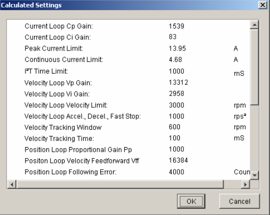
2. Verify the peak current limit, continuous current limit, and velocity loop velocity limit. If one or more of these values seems inappropriate, click Cancel and check: Peak Torque (or Force), Continuous Torque (or Force), Velocity Limit, and Torque (or Force) Constant. Correct them if needed. See Rotary Motor Setup Parameters or Linear Motor Setup Parameters.
If the Motor/Feedback values were correct but the peak current limit, continuous current limit, or velocity loop velocity limit values are not optimal for the application, change these limits during the tuning process.
3. Load the values into amplifier RAM by clicking OK.
NOTE: When loading motor data from a file, if the motor wiring configuration in the motor file does not match the configuration currently stored in the amplifier, CME prompts for verification on which configuration to use. Select the file configuration by clicking Yes. The configuration will be tested as part of Motor Phasing
4.  On the Main screen, click Save to Flash to avoid losing the changes.
Słowa kluczowe
Motor/Feedback, silnik obrotowy, silnik liniowy, stała momentu, indukcyjność, rezystancja, enkoder, resolwer, podwójne sprzężenie, hamulec, Brake/Stop, Calculate, plik .ccm
No comments to display
No comments to display