
4. Basic Setup
Streszczenie: Ekran Basic Setup: kreator zmiany ustawień wzmacniacza – opcje silnika, sprzężenia zwrotnego, trybu pracy (źródło zadawania, tryb prądowy/prędkościowy/pozycyjny) i opcje różne; szybka konfiguracja silników liniowych ServoTube.
EN: Basic Setup screen: motor, feedback, operating mode and miscellaneous options, plus ServoTube motor setup.
Dotyczy: program CME 2 do konfiguracji i strojenia serwonapędów oraz napędów krokowych Copley Controls (m.in. Xenus, Accelnet, Stepnet, Accelus, Junus)
Źródło: dokumentacja producenta (Copley Controls CME 2 User Guide); tabele przepisane z obrazów na tekst – opracowanie Multiprojekt
This chapter describes the Basic Setup screen. Perform the basic steps outlined below to access and enter the Basic Setup options. Details follow in the chapter.
1.  Click to open the Basic Setup screen.
2. 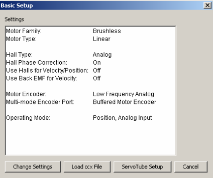
3. Review settings.
4. Choose:
 If necessary, click Change Settings to Change Basic Setup Settings
OR  If you have a .ccx file that was prepared for the amplifier/motor combination, click Load ccx File and see Copy Amplifier Data
OR  To change Basic Setup settings for a ServoTube motor, click ServoTube Setup and see ServoTube Setup
OR  To accept the displayed settings, click Cancel.
4.1 Change Basic Setup Settings
1.  On the Basic Setup screen, click Change Settings to start the Basic Setup wizard. Use the Back and Next buttons to navigate screens. Screen details vary depending on amplifier model and mode selection.
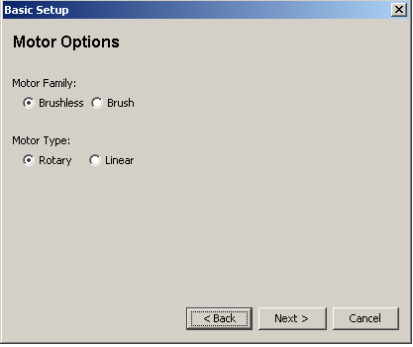
2. Set Motor Options
3. Set Feedback Options
4. Set Operating Mode Options
5. Set Miscellaneous Options
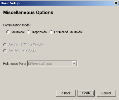
6. When satisfied with the settings, click Finish on the final screen.
4.2 Motor Options
View or change the settings described below. Options vary with amplifier model
| Setting | Description |
|---|---|
| Motor Family | Select motor family: Brushless, Brush, or Three Phase Stepper. (Three Phase Stepper configures the amplifier to operate as an open-loop stepper drive for three-phase stepper motors.) |
| Motor Type | Select motor type: Rotary or Linear. |
4.3 Feedback Options
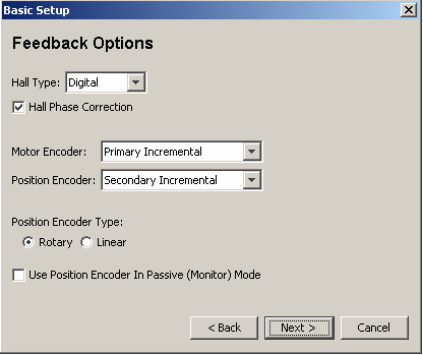
View or change the settings described below. Options vary with amplifier model.
Basic Setup – Feedback Options
| Setting | Description |
|---|---|
| Hall Type | Select Hall type: None, Digital, or Analog (Analog is used with Copley Controls ServoTube motors). |
| Hall Phase Correction | If selected, will enable error checking between Hall switches and encoder based phase angle. See Faults. |
| Motor Encoder | Select type and source of motor feedback: None – no motor encoder; Primary Incremental – incremental encoder on primary feedback connector; Secondary Incremental – incremental encoder on multi-mode port; Analog – analog encoder on primary feedback connector; Low Frequency Analog – Copley ServoTube motor on primary feedback connector; Resolver (Resolver version only) – resolver on primary feedback connector. Additional encoder types are supported by certain Copley Controls amplifier models. See the amplifier data sheet for more information. |
| Position Encoder | Select type and source of Position (load) feedback: None – no position encoder; Primary Incremental – incremental encoder on primary feedback connector; Secondary Incremental – incremental encoder on multi-mode port; Analog – analog encoder on primary feedback connector. |
| Position Encoder Type | Select the type of Position (load) encoder: Rotary or Linear. |
| Use Position Encoder in Passive (Monitor) Mode | When this is checked, the position of the position encoder will be reported by the passive load position variable but it will not be used to control the position of the axis. |
| Stepper Amplifiers Only | |
| Motor Encoder | Select the encoder type: None or Primary incremental. |
| Run in Servo Mode | (With encoder only.) Amplifier operates as a true, closed loop, servo amplifier controlling a stepper motor. |
| Enable Encoder Correction | (With encoder only.) Amplifier runs as a stepper drive; encoder feedback is used to correct positional errors. See Encoder Correction. |
4.4 Operating Mode Options
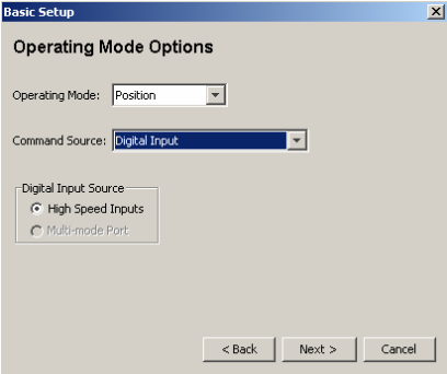
View or change the settings described below. Options vary with amplifier model.
Basic Setup – Operating Mode Options
| Setting | Description |
|---|---|
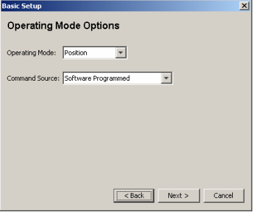
| Operating Mode | Choose the mode of operation: Current, Velocity, or Position. See Servo Operating Modes and Control Loops. |
| Command Source | Choose the command input source: Analog Command – analog voltage provides command input (see Command Inputs); PWM command (current and velocity mode only) – digital pulse-width modulated signal provides command input (see Command Inputs); Function Generator – internal function generator provides command input; Software Programmed – the amplifier is controlled by software commands from either the Copley Virtual Machine (CVM) or an external source (see Copley Indexer Program User’s Guide or the Copley ASCII Interface Programmer’s Guide); Camming – runs in Camming Mode (see Copley Camming User Guide); Digital Input – command input is provided via the chosen Input Source (below), see Digital Position Input Settings; CAN – command input is provided over the CANopen network (see the CANopen Programmer’s Guide). |
| Input Source | Choose the input source for PWM or Digital input commands: Single-ended Inputs – command input is provided via two of the amplifier’s programmable digital inputs; Multi-mode Port – command input is provided via differential inputs on the amplifier’s multi-mode port; Differential Inputs – command is provided via differential inputs; High Speed Inputs – command is provided via two of the amplifier’s high speed inputs. |
4.5 Miscellaneous Options
View or change the settings described below. Options vary with amplifier model.
Basic Setup – Commutation and Multi-mode Port
| Setting | Description |
|---|---|
| Commutation | Commutation method: Sinusoidal, Trapezoidal, or Estimated Sinusoidal. |
| Use back EMF for Velocity | If selected, will use the motor’s measured back EMF to determine motor velocity. Recommended only for medium- to high-speed. Accuracy depends on the accuracy of the programmed Back EMF value, and may be affected by factors such as cable resistance. |
| Use Halls for Velocity and Position | If selected, will use transitions of the Hall switches to determine motor velocity and position. Recommended only for medium- to high-speed applications (may run roughly at low speeds). |
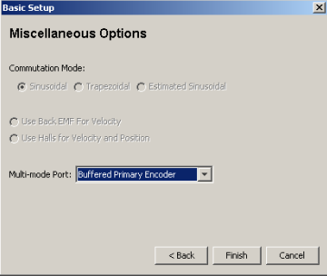
| Multi-mode Port | Selects the mode for the amplifier’s multi-mode port: Buffered Motor Encoder – the multi-mode port functions as a buffered digital encoder output based on the digital encoder input; Emulated Motor Encoder – the multi-mode port functions as an emulated digital encoder output based on the motor analog encoder or motor resolver; Emulated Position Encoder – the multi-mode port functions as an emulated digital encoder output based on the position analog encoder; Differential Input – the multi-mode port functions as a differential command input. |
4.6 ServoTube Setup
The ServoTube Setup tool sets up the amplifier for use with the chosen ServoTube motor. After the user selects the motor series and model, CME 2 performs the following actions:
- Sets motor-specific values for all feedback options in the Basic Setup screen.
- Provides motor-specific values for all settings in the Motor/Feedback screens.
- Performs the Calculate function to set initial gains and limits.
- Sets the appropriate programmable digital input as Motor Over Temperature.
- Phases the motor.
- Saves all values to flash.
- Opens the Control Panel so the user can Run a move in jog mode
Set Up a ServoTube Motor
1.  On the Basic Setup screen, Click ServoTube Setup to start the Basic Setup wizard. Use the Back and Next to move from screen to screen as needed.
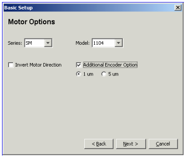
2. Choose the appropriate Series and Model. Optionally choose to Invert Motor Direction. Optionally choose the Additional Encoder Option (available with certain motor series) and choose the appropriate resolution for the optional encoder (1 um or 5 um).
3. Set Operating Mode Options
4. Set Miscellaneous Options
5. When satisfied with the settings, click Finish. The control panel opens.
6. To test basic move capabilities, Run a move in jog mode
7. Test with load attached
Słowa kluczowe
Basic Setup, kreator, typ silnika, sprzężenie zwrotne, enkoder, resolwer, czujniki Halla, tryb pracy, źródło komend, ServoTube, plik .ccx
No comments to display
No comments to display