
12. Stepper Controls
Streszczenie: Sterowanie silnikami krokowymi we wzmacniaczach Copley: obsługa trybu krokowego, limity pozycji, korekcja enkoderowa (Encoder Correction) oraz kompensacja momentu zaczepowego (Detent Compensation Gain).
EN: Stepper controls: stepper motor support, position limits, encoder correction and detent compensation.
Dotyczy: program CME 2 do konfiguracji i strojenia serwonapędów oraz napędów krokowych Copley Controls (m.in. Xenus, Accelnet, Stepnet, Accelus, Junus)
Źródło: dokumentacja producenta (Copley Controls CME 2 User Guide); tabele przepisane z obrazów na tekst – opracowanie Multiprojekt
This chapter describes set up and tuning steps that are particular to stepper amplifiers. The basic operations are listed below. Details follow in the chapter.
 Set Position Limits in Stepper Mode (p. 123).
 Set Encoder Correction Gain (p. 125).
 Tune Stepper Detent Gain (p. 126).
12.1 Stepper Motor Support
CME 2 supports Copley’s stepper amplifier family. Stepper amplifiers can run in stepper mode or servo mode.
This chapter describes controls that can be used to fine-tune a stepper amplifier in stepper mode: Encoder Correction and Detent Compensation Gain. It also describes the screen used in stepper mode to set Position Limits.
When a stepper amplifier is used in servo mode, it operates as a true, closed loop, servo amplifier controlling a stepper motor. After putting the stepper amplifier into servo mode, set it up and tune it just as you would a servo amplifier.
12.2 Position Limits (Stepper Amplifier)
Perform the following steps to set position limits for a stepper amplifier connected to an encoder with Encoder Correction enabled (not operating in Servo mode).
Set Position Limits in Stepper Mode
1.  Click to open the stepper Position Limits screen. Click the Trajectory Values tab.
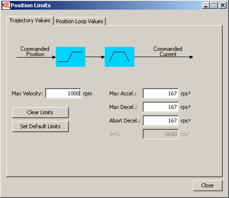
2. Change/verify the values as needed:
Stepper trajectory limits
| Parameter | Description |
|---|---|
| Max Velocity | Maximum trajectory velocity. Max value may depend upon the back EMF and the Max feedback count. Min: 0. Default: 0.25 x motor velocity limit. |
| Max Accel | Maximum trajectory acceleration. Max value may depend upon the load inertia and peak current. Min: 0. Default: 0.5 x velocity loop Accel. Limit value. |
| Max Decel | Maximum trajectory deceleration. Max value may depend upon the load inertia and peak current. Min: 0 (disables limit). Default: 0.5 x velocity loop Accel. Limit value. |
| Abort Decel | Deceleration rate used by the trajectory generator when motion is aborted. Min: 0. Default: 0.5 x velocity loop Accel. Limit value. |
| Note that setting limits to zero disables the trajectory generator so that the command input is not limited by the generator. Velocity is only limited by the Velocity Limit set in the Velocity Loop. | |
3. Click the Position Loop Values tab:
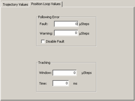
4. Change/verify the values as needed:
Stepper position loop – following error and tracking limits
| Limit | Description |
|---|---|
| Following Error | |
| Fault | The level (in encoder counts) at which the following error produces a fault, which stops the servo loop. We recommend raising the fault level before tuning the loop. See Following Error Fault Details. |
| Warning | The level (in counts) at which the following error produces a warning (without stopping the loop). See Following Error Fault Details. |
| Disable Fault | Stops following error from faulting. See Following Error Fault Details. |
| Tracking | |
| Window | Width of tracking window in counts. See Tracking Window Details. |
| Time | Position must remain in the tracking window for this amount of time to be considered tracking. See Tracking Window Details. |
5. Click Close to close the window.
6.  On the CME 2 Main screen, click Save to Flash
12.3 Encoder Correction
For a stepper motor with an encoder, Encoder Correction proportional gain can be used to compensate for lost microsteps.
Set Encoder Correction Gain
1.  Click to open the Encoder Correction screen.
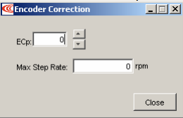
2. Set the Encoder Correction parameters:
Encoder Correction – parameters
| Parameter | Description |
|---|---|
| ECp | Proportional gain used to compensate for lost microsteps. Default: 0. |
| Max Step Rate | Maximum velocity allowed while using ECp to correct position errors. Excessive velocity can result in more lost microsteps. Default: 0. |
12.4 Detent Compensation Gain
Stepper motors are subject to torque detent that can cause undesired velocity fluctuation between full steps of motion. The Detent gain feature can compensate for this detent.
Tune Stepper Detent Gain
1.  Click Detent to open the stepper amplifier Advanced Tuning screen.
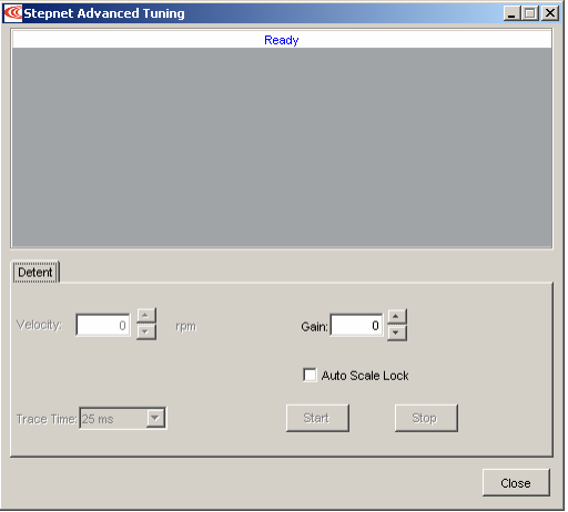
Screen settings and controls are described below:
Detent compensation – settings
| Setting | Description |
|---|---|
| Velocity | Tuning velocity. Default: 0. |
| Trace Time | Length of trace interval to be shown on screen. Default: 25 ms. |
| Gain (Detent Gain) | The Stepper Detent Gain value. Default: 0. |
| Auto Scale Lock | When selected, prevents trace display from rescaling during tuning. |
2. Click Start to begin the tuning.
3. Adjust Velocity from 0 until the mechanical system begins to resonate. (Using a 1.8 degree step motor with 200 full steps, this will typically occur at a velocity of 40-70 rpm.)
4. Adjust Gain until the resonance increases, and then back it down until the resonance is minimized.
5. Click Stop to stop the tuning.
6. Click Close to close the window.
7 On the CME 2 Main screen, click Save to Flash
Słowa kluczowe
silnik krokowy, Stepnet, tryb krokowy, limity pozycji, encoder correction, detent, kompensacja, strojenie
No comments to display
No comments to display